Here are the machine elements that have been employed in automatic machines for a long timeBasics that designers need to keep in mind about the chain.Note the
Chain usage" is an extremely important factor that determines the reliability of equipment. There are many sites on the Internet that list manufacturers' catalog figures and product specifications, but the actual design practice confronts us with questions such as "Why should we choose that chain?" and "What should be the specific arrangement and adjustment to avoid causing trouble in the field?Surprisingly little information that goes deeply into the designers' decision criteria. It is a thing.
In this section, I have not merely reproduced catalog information, but have systematized know-how (from basic knowledge to the theory necessary for machine design) that is relevant to practical use, based on my practical experience as well as thorough research of each manufacturer's vast technical data and the latest maintenance guidelines. I hope you will find it useful.
Basic use of chains in machine design
The basic principle of a chain is sliding between a pin and a bush.
The first and most important thing to understand when designing a machine using chainsThe core mechanism is the internal action of the chain as it bendsThe chain is a sprocket. From the outside, it appears that the chain just wraps around the sprockets and moves smoothly, but inside the chain, extremely severe and important "sliding" is taking place. Specifically, the "pin" fixed to the outer link rotates within the cylindrical "bush" (not a bushing) fixed to the inner link.
This pin and bush relationship is exactly the same structure as that of a "plain bearing" in mechanical engineering.As the links change angles when the chain engages or disengages the sprockets, friction occurs at this contact surface. This sliding part is the heart that controls the performance and life of the chain,Without an adequate lubricant film here, metal-to-metal contact occurs directly, resulting in rapid frictional heat and wear.The first thing to do is to make sure the product is not a "one-size-fits-all" product.
As wear progresses, the outer diameter of the pin is shaved and thinner, and the inner diameter of the bush is shaved and wider. This increases the rattling (gap) between each link, resulting in a physical elongation of the entire chain length.This is called "wear elongation. When designers calculate the durability of a chain, it is essential to consider not only the tensile strength but also the surface pressure (bearing pressure) applied to the contact area (projected area) between this pin and bush, and to create an environment at the design stage where proper lubrication can be maintained. The ability of a machine to operate trouble-free over a long period of time depends on the creation of an environment for these minute sliding parts.
Structure and role of rollers and plates
Pins and bushes are not the only components of a chain. Plates and rollers also play a decisive role in the chain system. Understanding the role of each of these parts accurately enables appropriate selection.
First, the "plates (inner and outer plates)" are the main strength members that support the powerful tensile load (tension) applied to the chain. The plates must have high "fatigue strength" to withstand repeated variable loads and "impact strength" to withstand shocks at startup or sudden stop. Therefore, carefully selected special steel is heat-treated to achieve both tenacity and hardness.The thickness and shape of the plate (e.g. gourd shape) is the biggest factor in determining the allowable tension of that chainwill be.
Next, the "roller" is a cylindrical component that is freely rotatable and fits on the outside of the bush. When the chain comes into contact with the sprocket teeth, the roller rotates and contacts the tooth surface. This "rolling contact" reduces the impact during engagement and dramatically reduces frictional resistance against the tooth flanks. If the rollers were not present in a bush chain, the contact with the teeth would be "slippage," causing severe wear and noise.The rollers ensure smooth transmission and long life of the sprockets and chain itself.The first is the
What is Pitch? Definition of Basic Dimensions
Pitch" is the most fundamental dimensional index for selecting chain sizes and specifications. Pitch is the distance from the center of adjacent pins to the center of the pin. This dimension is the absolute reference value that determines the size of the chain, its transmission capacity, and the size of the sprocket.
機In machine design, pitch selection is synonymous with determining the "scale" of the machine. A chain with a larger pitch can transmit more power and load because its components (pins, plates, and rollers) are larger and sturdier. However, a larger pitch increases the mass of the chain, increases the unit cost of parts, and tends to increase noise and vibration due to polygonal motion at high speeds.
On the other hand, chains with a smaller pitch are lighter, quieter, and can use smaller diameter sprockets, which is advantageous for space saving, but the torque that can be transmitted is smaller. The nominal number of a chain (e.g., RS40, RS80, etc.) specified in JIS (JIS B 1801) and ANSI standards is based on this pitch. For example, RS40 is approximately 12.7 mm (4/8 inch) and RS80 is 25.4 mm (8/8 inch),Pitch settings based on inch units are common. The designer must weigh the three factors of required power, installation space, and rotational speed to select the chain size with the optimum pitch.
Comparison of characteristics with belts and gears
In addition to chains, there are other options for power transmission, such as V-belts, timing belts, and gears (gears).For optimal design, the advantages and disadvantages of each should be compared in detail to determine the situations where the chain is most effective.The following table summarizes a comparison of the characteristics of the main transmission elements.
Table 1: Comparison of characteristics of major power transmission elements
| Comparison items | roller chain | V-belt | timing belt | Gears |
| Synchronization (rotation ratio) | ant (No slip) | None (with slip) | ant (No slip) | ant (Accurate) |
| Transmission torque/load | 大 (High torque and impact resistance) | Medium to small | Medium (with risk of tooth skipping) | extra-large |
| Degree of freedom of inter-axis distance | 大 (Short to long distance) | Medium (may not be suitable for long distances) | 中 | Small (axes must be close to each other) |
| Noise and Vibration | Large (with metallic contact sound) | 小 (Excellent quietness) | Medium (roaring sound at high speed) | Medium, depending on accuracy |
| Lubrication needs | indispensable (except for lubrication-free type) | unnecessary | unnecessary | indispensable |
| Environmental resistance (heat, oil) | 高 (Metal and resistant) | Low (easily degraded by oil and heat) | Low (rubber/resin degradation) | 高 |
| initial cost | 中 | 低 | Middle to High | (Processing and assembly costs) |
| maintenance | Lubrication and elongation adjustment required | Tension adjustment/replacement required | Tension adjustment required | Refueling management required |
Reference Source:
- Tsubakimoto Chain Co.https://tt-net.tsubakimoto.co.jp/tecs/engd/cdc/engd_cdc.asp)
- The Japan Society of Mechanical Engineers (https://www.jsme.or.jp/jsme-medwiki/doku.php?id=16:1011877)
As this comparison shows,Chains are a powerful option in situations where "large torque is reliably transmitted between distant shafts without slipping. The true value of a chain is demonstrated in harsh environments where belts would slip, or when connecting distances that gears cannot reach.
Why is synchronous transmission possible?
The engineering reason why chain transmission can achieve "synchronous transmission" is that its transmission mechanism is based on "mechanical engagement (Positive Drive)" rather than frictional force. V-belts and flat belts rely on the frictional force between the pulleys and the belt to transmit power, so when tension decreases due to overloading or deterioration over time, "slippage" occurs, resulting in a shift in rotation speed.
In contrast, a chain transmits power by physically meshing the "teeth" of the sprockets with the "rollers" of the chain. Due to this structure, the "speed ratio" of how many degrees the output shaft (driven side) rotates when the input shaft (driven side) makes one revolution is,Completely fixed by sprocket tooth ratioIf the drive side has 10 teeth, the driven side will make exactly one revolution. For example, if the drive side has 10 teeth and the driven side has 20 teeth, then when the drive side makes two revolutions, the driven side makes exactly one revolution. Unless the chain is broken or a tooth is chipped, this synchronous relationship will not be disrupted.
This characteristic is decisive in applications where the timing of multiple axes must be perfectly matched, such as automatic assembly machines and conveyor systems. Timing belts have similar synchronization properties, though,Since the chain is made of metal, it is more rigid than rubber or plastic belts, and has extremely low expansion and contraction (elastic deformation) due to load fluctuations, making it superior in positioning accuracy and ability to maintain synchronization under heavier loads.
How to use different types of chains for different machines
Power transmission and transport attachments
Chain applications can be broadly classified into two categories: power transmission (drive) and conveyance (conveyor). The main purpose of power transmission chains is to transmit the rotational energy of a motor to the main shaft of a machine with high efficiency, requiring high speed rotation and high fatigue strength. On the other hand, the main purpose of chains for conveyance is to load a workpiece (conveyance object) on the chain itself or to move it by attaching a jig to it,Diverse attachments are key.will be.
One of the most important elements in a conveyor chain is the attachment. These are standard link plates or pins that have been partially deformed or extended to provide holes or protrusions for securing the material to be conveyed. Typical attachments include the following types
Table 2: Typical attachment types and features
| Attachment Name | symbol | Shape Features | Main applications and uses |
| A Attachment | A1/A2 | Shaped with a horizontal seat plate (with holes) on one side. | Installation of slats (boards) and buckets. Most common. |
| K Attachment | K1/K2 | Shaped with horizontal seat plates (with holes) on both sides. | Used to secure wide slats and stable conveying objects. |
| SA Attachment | SA1/SA2 | Shaped with a vertical seat plate (with holes) on one side. | Used for bars that push workpieces from the side and for fixing vertical surfaces. |
| SK Attachment | SK1/SK2 | Shaped with vertical seat plates (with holes) on both sides. | Installation of attachments and guides that push from behind the workpiece. |
| EP Attachment | EP | Shape in which one end of the pin protrudes long. | Hang a workpiece directly on the extension pin or attach a guide roller. |
| hollow pin | home page | A shape in which the pin itself is hollow (pipe-like). | Connect the left and right chains by passing the bar (rod) through the hole in the pin. |
| G Attachment | G | Shaped with a hole in the center of the plate. | There is a hole in the plate of the pin link, through which a bar or other object is threaded. |
*The numbers (1, 2) in the symbols indicate the number of mounting holes (e.g., A1 has 1 hole, A2 has 2 holes).
Reference Source:
- Tsubakimoto Chain Co.https://tt-net.tsubakimoto.co.jp/tecs/pdct/csc/pdct_csc_1cshn.asp?lang=jp)
- KCM (http://www.kcm.co.jp/product/kogata/index.html)
The designer selects the best attachments according to "what" and "how" he/she wants to transport, and further specifies "how many links" to attach them every other link (organization).The manufacturer recommends that attachments be installed on even links (2L, 4L...). The manufacturer's recommendation is to install attachments on even links (2L, 4L...) on the "outer link" for ease of maintenance.
Basic RS roller chain
The RS roller chain is the most widely used chain in the world and is synonymous with the chain. It conforms to JIS standards (JIS B 1801) and ANSI standards, and is compatible with products from any manufacturer, making it extremely easy to obtain. When designing a machine, unless there are special circumstances or restrictions, the theory is to start with the RS roller chain as the standard for consideration.
RS roller chains offer an excellent balance of tensile strength, abrasion resistance, impact resistance, and cost performance. A wide range of sizes (nominal numbers) are available, from very small sizes used for precision equipment to huge sizes for heavy industries. Generally, carbon steel and alloy steel are used as materials, and strength is ensured through appropriate heat treatment.
However,The standard RS roller chain is made of steel, which rusts easily in watery environments and requires regular lubrication.It is. In corrosive environments or special environments such as clean rooms, though, it is necessary to switch to stainless steel, surface-treated specifications, or oilless chains,Those special chains also often conform to RS roller chains in their basic dimensions.Therefore, the starting point for design is to first understand the specifications of this chain.
Bipitch chain suitable for long-distance transport
In conveyors and other conveying equipment,When designing long lines with machine lengths exceeding several meters, "bi-pitch chains" are very often used instead of standard RS roller chains. As the name suggests, a bipitch chain is a chain with the pitch dimension of the RS roller chain stretched to "double pitch" (Double Pitch).
The greatest benefit of doubling the pitch is a significant weight reduction and lower cost. For example, if a conveyor with a total length of 10 meters is to be made, only half as many pins and bushings are needed as for the RS chain if the pitch is doubled. This reduces the weight of the chain itself and the load on the drive motor. The reduced number of parts also reduces the product price.
In addition, two types of rollers are available for bipitch chains: "R roller (large diameter roller)" and "S roller (standard diameter roller). The R roller type, in particular, is designed so that the outer diameter of the rollers is larger than the width of the plate, allowing the chain itself to roll and run on the rails. This dramatically reduces running resistance (friction), allowing long, heavy lines to run smoothly with little power. For low-speed, long-distance conveying, bi-pitch chains are by far the more rational and economical choice than RS roller chains.
Utilization of lubrication-free chains that do not require refueling
Oilless chains (e.g., lambda chains) were developed to solve the biggest concern for machine designers when adopting chains: lubrication control (oil supply). Demand for lubrication-free chains is increasing year by year in food production lines, pharmaceutical facilities, printing and packaging machines, and other environments where oil contamination on products is not desirable or where maintenance time for lubrication work cannot be allocated.
The most distinctive feature of the oilless chain is the use of "oil-impregnated sintered metal" for the bush. This special bush is impregnated with a large amount of lubricating oil at the manufacturing stage. When the chain is running and the pin and bush slide against each other, generating heat and pressure, oil slowly seeps out from the minute pores inside the bush and automatically lubricates the sliding surfaces. When the machine is stopped, the oil returns to the inside of the bush by capillary action. This autonomous lubrication cycle allows the product to continue to be used for a long period of time without external lubrication, thereby reducing wear growth.
However, there are also considerations to be made for oilless chains. Oil-impregnated bushings may have slightly less acceptable surface pressure and impact strength than normal steel bushings, and their operating temperature range depends on the properties of the oil in which they are sealed.
Standard types are generally available from -10°C to 150°C, but some heat-resistant specifications (e.g., KF specifications) can be used up to 230°C. Designers need to carefully check the "allowable tension" and "operating temperature range" in the catalog and determine the balance between merits and limitations before adopting the product.
How to use chain selection to support advanced machine design
Sprockets key to selection
In selecting a chain, the selection of "sprockets (gears)" is as important as, or more important than, the specifications of the chain itself. Since the chain and sprockets function as a complete pair of systems, if the sprockets are of improper quality or specifications, no matter how expensive the chain, it will not perform at its full potential.
Sprockets are conversion devices that convert rotational power into chain tension and vice versa. Of particular importance is the hardness of the tooth tips. When used frequently or in an environment where they are subject to wear due to the presence of dirt, sand, or dust, sprocket tooth tips should be hardened to a "hardness" of "0.5 to 0.5" (0.005 mm).Tooth tip hardening treatment (e.g., high-frequency quenching)It is strongly recommended to choose a specification that has been given a "B" rating.If the tooth tips become worn and skinny, the mesh pitch with the chain will be out of alignment and the chain rollers will be subjected to excessive force, shortening their life span and causing vibration and noise.
The machining of sprocket shaft holes also affects design efficiency. If you choose "finished sprockets" with shaft holes, key grooves, and set screws machined in advance, you can save time and effort in design and procurement. On the other hand, if the sprocket is to be installed on a special shaft, you will need to select a "pre-drilled" sprocket and perform additional processing. Selecting the proper sprocket is an act that underlies the reliability of the chain system.
How to determine the number of teeth on a sprocket
Sprocket "tooth count" is a critical parameter that determines chain life, transmission efficiency, noise level, and equipment size. The designer must determine the number of teeth not only to obtain the required reduction ratio, but also with a view to minimizing the load on the chain.
The number of teeth on the small sprocket (drive side) is,make as much of it as possibleThis is an ironclad rule of design. When the number of teeth is small, the trajectory of the chain as it wraps around the sprockets is less circular, and polygonal motion (polygon effect, or "crunching") becomes more pronounced. This is a phenomenon in which the chain moves in a pulsating motion, creating vibration and shock loads that accelerate fatigue failure and uneven wear of the chain. Generally, the number of teeth on a small sprocket isAt least 15 sheets, preferably 17 or moreIt is recommended that the number of teeth be selected to be as low as possible. Even if it is absolutely necessary to reduce the number of teeth due to space limitations, we should avoid 13 or fewer as much as possible.
On the other hand, there is also an upper limit to the number of teeth on the large sprocket (driven side). In general, when the number of teeth exceeds 120 or so, even a slight increase in chain wear increases the risk of "tooth skipping," in which the engagement position of the chain with the teeth shifts significantly and the chain overcomes the teeth.Finding the balance between keeping the number of teeth on the small sprocket and not overloading the large sprocket, usually within a reduction ratio of up to about 1:7, is where the skill of a good designer comes in.
Correction factor to account for load variations
The chain's transmission capacity (kW) listed in the manufacturer's catalog is based on ideal conditions of "uniform load, 8 hours of operation per day, and proper lubrication. However, most actual machines are used under harsh conditions, such as frequent startup and shutdown, shock loads, or continuous 24-hour operation. Selection without taking these factors into account may result in the risk of premature failure. This is where the "correction factor (usage factor Ks)" comes in.
The correction factor is determined from a matrix of "type of prime mover" and "nature of load". The following table is a general guide to correction factors.
Table 3: Usage Factors (Service Factor: Ks)
| Nature of the load (type of impact) | Examples of machines used | Prime mover: Electric motor, turbine | Prime mover: Internal combustion engine |
| uniform load (No impact) | Conveyor (uniform), fan, pump | 1.0 | 1.2 |
| minor collision (some impact) | Conveyors (non-uniform), machine tools, compressors | 1.3 | 1.4 |
| heavy impact (Big shock) | Presses, crushers, construction machinery | 1.5 | 1.7 |
*The above is a general guideline and values may vary depending on the manufacturer and type of chain (e.g., strong chain).
Reference Source:
- Tsubakimoto Chain Co.https://tt-net.tsubakimoto.co.jp/tecs/engd/cdc/engd_cdc_sen_tok.asp?lang=jp)
- RK Japan K.K. (http://www.rk-japan.co.jp/sangyou/chain_selection/)
In the selection calculation, the "corrected power (design power)" is calculated by multiplying the actual power (kW) to be transmitted by this correction factor, and the chain size that satisfies this value is selected. For example, if a machine with a shock has a motor output of 10 kW, but the coefficient is 1.5, a chain that can withstand 15 kW must be selected. This is the "safety margin" that ensures the safety and longevity of the machine.
Calculation of allowable tension to ensure safety
There are two approaches to chain selection: selection based on "power (kW)" (mainly in the high-speed range) and selection based on "tension (kN)" (mainly in the low-speed range). Especially for conveyors, lifting devices, or applications where high torque is applied at low speeds (e.g., below 50 rpm), the "maximum tension" acting on the chain is calculated in addition to the power selection, and it isCheck that the "maximum allowable tension" of the chain is not exceeded. It is essential to
The maximum allowable tension is the load limit at which the chain can be used without fatigue failure and without harmful plastic deformation (initial elongation). In the calculation, the theoretical tension acting on the chain is first determined from the motor torque and sprocket radius. The correction factor mentioned above, the speed coefficient corresponding to the chain speed, and the multi-row coefficient in the case of a multi-row chain are then added to calculate the actual maximum load acting on the chain.
In particular, leaf chains used for lifting and lowering applications that involve human life and safety, such as forklifts and cranes, are subject to legal regulations and standards (ISO, JIS D 6001, etc.), which require that the breaking strength of the chain be5 times or moremay be required or recommended to ensure a safety factor of
To ensure that the design is not only "unbreakable" but also "safe to use with a margin of safety," the allowable tension must be strictly checked.
How to calculate the number of links and distance between axes
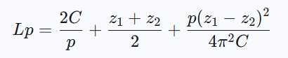
Once the chain size and sprockets are determined, the next step is to calculate the layout. How far apart are the two axles (distance between axles)? C)" and "How many links are required for the total length of the chain (number of links) Lp)" are calculated accurately. These are related to each other and are determined using the following formulas
Table 4: Formulas for calculating the distance between axes and number of links
| Objective. | Formula (Approximate formula) |
| 1. distance between axes (C) from
Number of links (Lp) for a given |
 |
| 2. number of links (Lp) from
The distance between the axes (C) for a given |
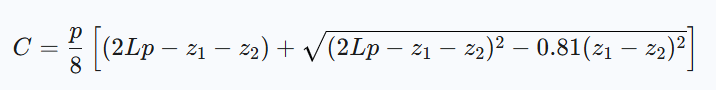 |
- Symbols: (a) LpTags: number of links, C: Distance between axes (mm), : Distance between axes (mm), : Distance between axes (mm), pChain pitch (mm), : Chain pitch (mm), : Chain pitch (mm), : Chain pitch (mm), : Chain pitch (mm), z1Sprocket Tooth Count, Large Sprocket Tooth Count, Large Sprocket Tooth Count, z2: number of small sprocket teeth, π: pi (approx. 3.14)
- Caution: The in the third term of Equation 1. 4π^2 in Equation 2, or the inverse of 0.81 は 8/π^2 is an approximation of the
- Important: The Calculated. Lpis a fraction,Always round up to the nearest whole number (and even numbers are recommended)to the of that integer. Lp is substituted back into Equation 2 to obtain the exact inter-axial distance C is recalculated and reflected in the drawing.
Reference Source:
- RK Japan K.K. (http://www.rk-japan.co.jp/sangyou/chain_selection/selection_cal/)
Neglecting this calculation directly leads to elementary errors such as "the chain does not reach" or "too long to adjust". It is also extremely important to adjust the number of links in the calculation results so that they are always "even" in terms of maintainability, which will be explained in the next chapter. Currently, automatic calculation tools are available on the websites of various manufacturers, and the modern standard is to utilize these tools to determine the values without making mistakes.
Notes on how to use chains on machines that will not fail
Why design with even links?
When determining the number of links in a chain, there is an ironclad rule that designers should absolutely follow. It is.「Always make the total number of links in the chain an even number」This is what we mean. This is not just a recommendation, but a prerequisite to ensure machine reliability and ease of maintenance on site.
A chain consists of alternating inner and outer links. If the total number of links is even, one end of the chain will have inner links and the other will have outer links. In this case, a standard connecting component, the "joint link" (joint link), can be used to make a very easy and strong endless connection (to form a loop). The joint link is designed to be fixed with a clip or split pin, and can be easily attached and detached on site without the use of special tools.
If you design with an odd number of links, both ends will have the same links (e.g., inner links to each other) and cannot be connected with standard joint links. In order to establish odd links, we are forced to use a special "offset link," which has a major disadvantage that will be discussed below.The even-link design is the "correct" design, which is the simplest, most reliable, and easiest to procure parts for.
Why Offset Links Should Be Avoided
As mentioned earlier, odd-link connections require "offset links," but there are clear reasons why designers should avoid their use whenever possible. That is because the offset link is the entire chain.「Strength Bottlenecks (Weaknesses)」This is because it would be
Offset links have a special shape in which the plate is structurally curved and a single link functions as both an inner link and an outer link. Because of this curved shape, a bending moment is easily generated in the plate when tensile loads are applied, resulting in a significant reduction in fatigue strength compared to standard straight links. In general, the allowable tension at locations where offset links are used is less than the standard chain capacity ofApprox. 60% to 80%The strength of the chain will drop to In addition, for some environmentally resistant chains, such as stainless steel chains, the use of offset links itself is not recommended, or may further reduce strength.
In other words, no matter how strong a chain is selected, the inclusion of just one offset link limits the capacity of the entire chain system to that low level.To avoid this, the layout should be devised so that the total number of links is even at all costs by adjusting the number of teeth on the sprockets or slightly changing the distance between the shafts. Offset links should be regarded as a "last resort" when an even number cannot be achieved by any means.
Incidentally, the chain was purchased with a standard number of links,Cut to use if you want to make it a necessary linkHowever, the chain is one of the most time-consuming parts of the actual assembly process.
Proper chain slack management
In chain transmission, "slack" is not a bad thing; it is an essential element for proper operation. It does not need to be as tight as a V-belt, but too much slack can cause problems. Maintaining the "proper amount of slack" is the secret to extending chain life.
Generally, when the middle of the span (distance between axes) is pressed with a finger,Approx. 2% to 4% of inter-axial distance(21 TP3T or less for vertical arrangement or reverse operation) is considered to be the proper state to allow deflection. If there is too little slack and too much tension (overtension), the chain pins and bushings are constantly overloaded, which not only accelerates wear but also damages the bearings (bearings) and the shaft itself.
Conversely, too much slack causes the chain to "dance," rippling when starting and stopping, coming into contact with the surrounding covers, or in the worst case, coming off the sprockets or "tooth skipping" over the teeth.At the design stage, it is essential to provide a mechanism that allows the distance between shafts to be adjusted by sliding the motor base (take-up mechanism) and an auto tensioner (tension adjustment device) to adjust slack after operation. Especially in a vertical arrangement, the chain will try to move away from the lower sprocket under its own weight, requiring more severe slack control and pressing by the idler.
Alignment adjustment that determines life span
No matter how optimally a chain is selected, if the "alignment" (shaft alignment) is not correct at the time of installation, the chain will break in a short period of time. Alignment adjustment is the process of aligning the drive and driven shafts so that they are "level and parallel" and the two sprockets are "on the same plane.
If the alignment is off, the chain will rotate while the inner side of the plate of the chain continues to strongly contact the side of the sprocket teeth. This causes uneven wear that shaves the plate, and the sprocket teeth are also shaved into an abnormal shape. In addition, the forced force in the twisting direction is applied to the pins and bushings, resulting in progressive localized wear and dramatically shortening the life of the chain.The manufacturer's recommended values include strict standards such as shaft parallelism within ±1/300 and sprocket face offset within 1/1000 of the distance between shafts (or an allowable value of approximately 1 mm).
The designer must design a structure that is easy to align. For example, consideration must be given to making a structure that allows adjustment of the sprocket boss positions and to machining the bearing mounting surfaces to a high degree of precision.The maintenance manual should also specify the procedure for checking alignment using a ruler, level, or laser measuring device, and should encourage periodic checks.
How to use chain characteristics in machine design
Elongation due to wear is a sign of life span
Chains "stretch" after prolonged use, but this does not mean that the metal plates are stretched like rubber. As explained at the beginning of the article, as the pins and bushings wear due to sliding and the gap (rattling) between them increases, the pitch of each link widens slightly, resulting in a longer overall chain. This "wear elongation" is the most reliable indicator of chain life.
Generally, the length of the chain is initially1.5% to 2.0% The point at which the sprocket extends is considered to be the standard replacement time (life span). If the sprocket has a large number of teeth (e.g., 60 or more teeth), the allowable range becomes narrower, and the life of the chain may be reached at around 0.8% to 1.2%. Continued use beyond this limit will cause the pitch of the chain and the pitch of the sprocket teeth to mismatch, and the chain will ride up on the tips of the sprocket teeth. This is a dangerous condition that causes severe vibration and noise and eventually leads to tooth skipping and breakage.
Table 5: Approximate wear elongation limit of the chain
| Number of teeth on large sprocket | Allowable elongation (%) |
| 60 teeth or less | 1.5% (General standard) |
| 61-80 teeth | 1.2% |
| 81-100 teeth | 1.0% |
| 101-110 teeth | 0.8% |
Reference Source:
- Tsubakimoto Chain Co.https://tt-net.tsubakimoto.co.jp/tecs/engd/cdc/engd_cdc_tri_tkn.asp?lang=jp)
The machine designer must assume that the chain will elongate and include in the design an adjustment allowance (take-up amount) that can absorb the amount of elongation. It is also important to recommend the use of a chain checker (wear measurement scale) and provide a window for inspection so that maintenance personnel can periodically measure the rate of chain elongation. Replacing the chain without overlooking the sign of "elongation" before it breaks is the surest way to prevent sudden stoppage of the machine.
Summary of how to use the chain with the correct machine
This article has provided a comprehensive overview of the proper use of chains in machine design, from basic principles to selection, design calculations, and operational considerations. Chains, when properly designed and managed, are very robust and reliable machine elements. Finally, we will summarize some important points that designers should keep in mind.
- The operating principle of the chain is sliding between the pin and bush, and lubrication is the key to longevity
- RS chain for power transmission, bipitch chain for long-distance transport, etc., depending on the application.
- Design to take advantage of synchronization and greater layout flexibility compared to belts and gears
- The number of sprocket teeth should be 15 or more as much as possible to reduce vibration.
- Always multiply the calculation by a correction factor that matches the actual load.
- Always use an even number of links in a chain and avoid offset links, which reduce strength.
- Moderate sag (2% to 4%) and accurate alignment prevent problems
- The criterion for life is not "rupture" but "wear elongation of about 1.51 TP3T.
- In environments where refueling is difficult, consider adopting a lubrication-free chain from the initial stage
- Understand the characteristics of the chain and include a reasonable layout and maintenance environment in the design
- In calculating the safety factor, legal regulations, if any, are given top priority.
- Consider not only design calculations but also ease of assembly and adjustment in the field
- Do not judge uncertainties based on catalog figures alone, but use the manufacturer's technical data and support.
- Keep in mind that proper chain selection directly leads to cost reduction and reliability improvement of the entire machine.
- Always be aware of the relationship between "wear" and "lubrication" to build sustainable machine systems
That's it.