In this section, we will discuss the "what you need to know" when dealing with welded parts.How to read, insert, and think about welding symbolsHere is a note about "The
I sometimes deal with welding in mechanical design,Welding symbols may seem difficult for those who are new to working with them.
Welding symbols can be found in "JIS Z 3021 Welding symbols", but they are often complex expressions for detailed welding instructions, and the reality is that they are not always clear.Often drawings are available with simplified welding symbols.
The welding symbols are also based on JIS, but each company has its own rules and regulations, so it is difficult to understand welding symbols because specific examples are not available outside the company.
This article provides the minimum points to remember for beginners describing welding symbols.①(1) How to read and put welding symbols, (2) Concept of welding symbolsThis section is divided into two sections.
This article will help you to understand the meaning of difficult welding symbols and their laws, so please read this article if you have not been able to understand the JIS standards. If you look at JIS after reading this article, you will be able to understand more. You can also use it in practice.
How to read welding symbols
welding symbol
First of all, when you want to put in a welding symbol, this is the symbol you will see when you look it up.
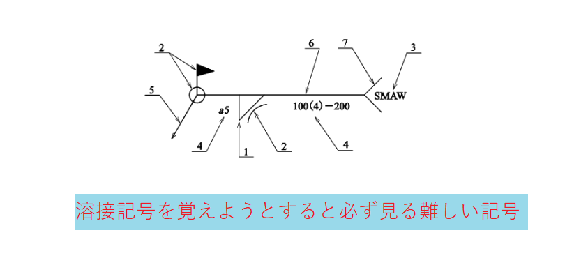
I see this out of the blue.Welding symbols are difficult.Although it will be,These symbols summarize all the information, and it is easier to understand if you read from the basic markings, so I will explain from there.
basic symbol
The first symbol in the welding symbols is shown below.

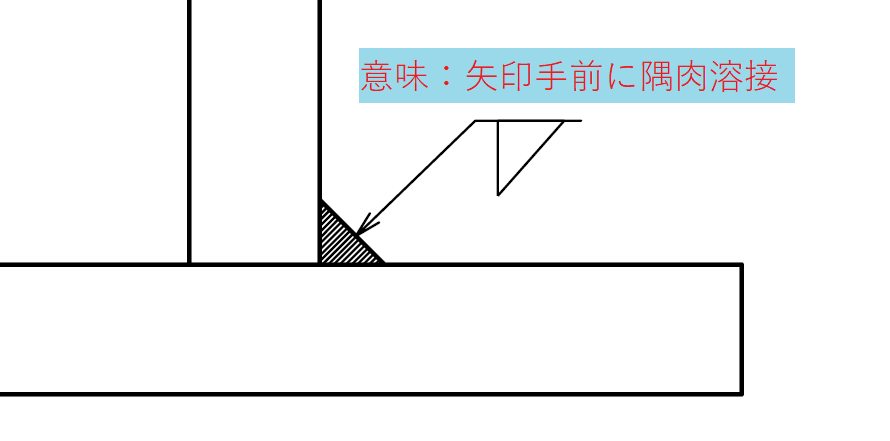
This is.It means, "I'm going to weld where this arrow points."will be. And thisPut instructions for what kind of welding to do below and above the baseline. base lineis parallel to the bottom of the figure frame, but a 90° rotated vertical is also acceptable in JIS.

Below this center line, called the baseline, is the front side, and above it is the opposite side. In other words, this is what it means.

The basic welding symbols used here (the symbol for "corner welding" in the figure above) have symbols for each of the various types of welding. Please refer to "JIS Z 3021 Welding symbols" for that.
Example of Broken Arrow Entry
What is a broken arrow?Used for pointing arrows at bevel surfaces utilized in groove weldingIt is. Bevel welding is a welding method in which the weld is heaped onto the plate. Bevel welding is a method of grinding the plate to be welded and applying the weld metal to it.
groove (in welding)
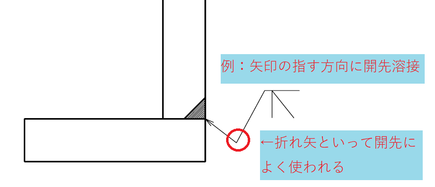
In mechanical design drawings, there are many drawings with pictures of welding,If there were an arrow without a broken arrow without a picture of the weld, I can't figure out which side of the board to cut.
Therefore, this broken arrow should point arrow toward the beveled face.
supplementary symbol (number, punctuation, etc.)
In addition to the basic welding symbols, auxiliary symbols are added to the welding symbols as necessary.
Typical auxiliary symbols such as "G" are sometimes added, meaning a grinder mark,Auxiliary symbol indication that the unevenness after welding should be removed.will be.

This is,Indicated when convexity is a problem, such as when parts are in contact next to each other.The following are some examples.
next
To make one round of welding, add a "0" as shown in the figure below. Now.It means, "Let me take a lap."will be.

In addition, since welding is sometimes done on site, a flag symbol signifying on-site welding is also added as necessary.
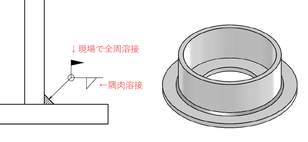
Situations in which on-site welding occurs include additional parts when existing opportunities do not allow them to be moved, and on-site installation of brackets to support piping.
How to read and use the welding symbol "tail
Next,Additional information, such as watertight welding, is listed as special instructions at < next to the base line (center line).The tail "<" is not used if it is not necessary. This tail "<" will not be filled in if it is not necessary.
For example, when using a component that is subject to water pressure, water leakage is not allowed, so instructions such as "watertight" should be placed in this location.
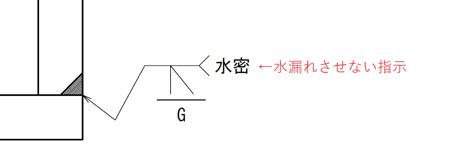
Strictly speaking, this is not enough for watertight welding,Regarding the degree of watertightness, it is necessary to specify in the drawings the test details to see if watertightness is achieved.
The contents to be described in the tail should include the JIS standard (quality grade) of the test to be applied, welding method, welding material, welding posture, etc. I have seen various drawings in the past, but each one is like the other,It is better to include a picture of the weld, because the risk of making a mistake is high for the creator if the picture does not show what kind of weld is being made.It is.
Concept of Welding Symbols
Instructions for obtaining welding quality
Next, we will discuss the instructions that determine the quality of the weld.
Actually,The explanation of welding symbols so far does not convey the "degree" of welding.
For example, for common sense strength or simple structures, a simple welding symbol may be requested, or there are drawings out there that simply say "welded structure" on the drawing. It isSometimes the welding symbols that designers instruct with the best of intentions are so excessive that they distort the actual product.It is.
converselyMost welding symbols used for mass-produced or heavy industry parts indicate the length of the weld, called the weld leg lengthIt is.
long-legged(ness)
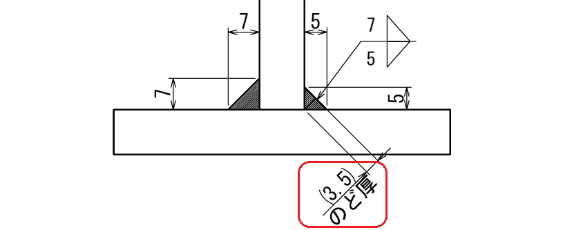
The leg length is used to give a dimensional indication of the size of the weld. If we include the leg length in the weld symbol we just used, we get this instruction.

This will mean "5 mm corner weld on the front side and 7 mm corner weld on the opposite side". This "5" and "7" are tentative by me, but some may use "4 x 6" or "3 x 5" when changing the length of the welding triangle shape. *I will use the tails at this time so that you can tell which is which.
gullet thickness
When indicating welding volume, in addition to leg length, there is also an indication called "throat thickness", but you don't need to worry about that at this point. (If you want to see it, check with JIS.)
This "throat thickness" is a dimension used for strength calculations (stress calculations) and other purposes.
Length of weld
Although not detailed here, welds are listed after the weld type if the length is specified.

It means length L=30mm, number of pieces=3, and pitch=60. However, since it is not clear from this symbol where the start point is, it would be better to include a picture of the weld on the flat surface and side surface and supplemental dimensions for this length specification.
summary
Let's look again at the welding symbols at the beginning of this story so far.
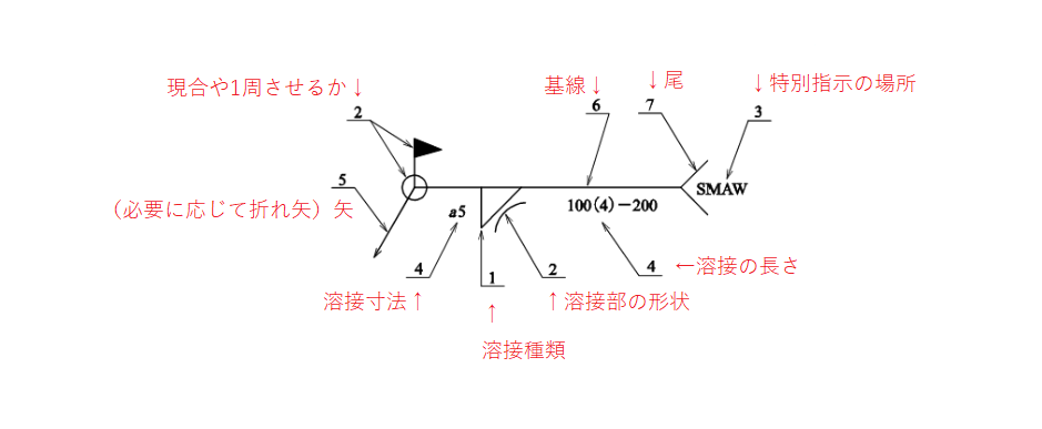
Thus, I think you can now read what is to be described where.
There are many types of welding, such as "corner welding in the front and bevel welding in the back," "butt welding," "plug welding," etc., depending on the situation, but it is OK to enter symbols with the basic points noted here in mind.
Finally.
Basic concept of how to determine welding and leg length
Finally, I would like to note my personal thoughts.
For those new to welding, you may be wondering how to decide on the type of welding and leg length. Some thoughts on the subject are
- Welding symbols for simple structures may not be needed if there are no special places to note
- Welding of parts to be made as products that require functionality in welding must be accurately weld symbolized.
I think it would be good if we could base our thinking on the idea that
For example, as a machining center or heavy industrial machinery.Welds that affect machine rigidity should dictate what the weld should be to fulfill that function, but for things like just putting something on the machine or something like that, it should be left to the welding fabricator.I think. (I can't find any reason to decide on a leg length and direct the welding of a trestle that is just to put things on it)
As I mentioned earlier, there are many situations in which the designer's one-sided writing will cause the fabricator to suffer, and it is necessary to ask the welding fabricator to write the welding symbols and the shape of the steel to be welded to give correct instructions. (In the first place, the cut shape of the steel material may not be the way the designer envisioned.)
Vs,Parts that require function and a certain quality are given precise welding instructions. Even if no special function is required, it is important to determine the degree of welding to determine the quality of the product for mass production. And since many of the welded parts tend to be large (heavy), welding strength is calculated to prevent accidents from occurring, and welding symbols that can satisfy the strength are inserted.
For example.Heavy industry products dictate welding with a level of detail far beyond what we can imagine!Sh,For large items, each part may be individually arranged before welding. In such cases, we draw a parts drawing with a beveled surface at the time of the parts drawing, taking welding into consideration.
That's it.
-

-
Introduction to Mechanical Drawing
Here, I would like to leave a note as an introduction to mechanical drawing, "Thorough Explanation from Basic Rules to Drawing Methods". In mechanical drafting, I have been wondering if I can really convey the ...
See more.
