Here, it is used to protect cables and hoses in machine drives. How to Select a Cable Carrier|BasicsI am making a note about the
In the design of FA automatic machines and industrial robots, how to safely protect the wiring of moving parts is a major theme that affects the reliability of the entire facility. In practical work, you may be faced with potential problems such as "Which parts should I choose to prevent early disconnection problems?", "Calculation of free span and storage ratio is too complicated to be confident", "I cannot read the actual durability in a harsh environment from catalog values alone", and you may be troubled by the fear of regret due to design errors. The following is a list of some of the most common problems that can be encountered in the design of a new product
Frankly, the selection can still be made for mass production machines, etc., since what goes into the cable bear (cable carrier) is almost always identified,In automated FA machines, it is difficult to know in detail "what goes inside and how" because each time a new design is made.
Therefore, although fragmentary know-how can be found on the Web, it is difficult to find comprehensive and systematic information directly related to actual equipment design.
I myself have experienced many failures and trial and error in the field of mechanical design. In this article, in addition to my past experiences, I have thoroughly researched the latest standards and manufacturers' technical data, which cannot be supplemented by experience alone, and compiled objective and detailed information that other sites lack.
This article is organized as a pillar page that allows readers to learn the overall picture of cable carriers in a broad and shallow manner, as well as the minimum knowledge required for practical use in a systematic manner. Specifically, the article starts with the basic product features and differences between major domestic and overseas manufacturers, and goes on to explain in detail the procedures for selecting the right material for the operating environment and calculating the length according to stroke. In addition, it provides complete answers to questions faced in practice, such as how to secure an appropriate storage ratio and how to utilize dividers to prevent wire breakage problems, as well as design standards that ultimately extend the life of equipment and compliance with standards required when exporting to overseas countries.
We hope that by reading through this information, especially for those new to design, it will be easier to find practical answers and acquire a standard base of knowledge on which to base your selection.
How to select cable bearers and manufacturers that will not fail
Essential basics about cable carriers
Wiring that supplies power and signals to the moving parts of a facility without interruption is the lifeline that keeps the entire system running.In machines that operate at high frequency, cable carriers are the mechanical elements that protect these wires from external obstacles and friction caused by self-intersections, and safely guide them along a fixed track.
In the Japanese design field, this component is often referred to as a cable bear, which is a registered trademark owned by Tsubakimoto Chain Co. This is a registered trademark owned by Tsubakimoto Chain Co.
On the other hand,When preparing official drawings or discussing specifications with other companies, the key to clearly communicating your intentions to others is to accurately use common names such as cable carrier and energy chain, as well as the trademarks of each company. Continued machine operation without wiring protection increases the risk of unexpected line stoppages and huge repair costs due to metal fatigue and severe wear of the coating. To prevent this from happening and ensure the stable operation of equipment, it is essential to employ the most appropriate protective components with the correct basic knowledge.
Major domestic and international manufacturers and product types
In selecting protective components, knowing what products exist on the market and from which suppliers is a very useful approach. Currently, several manufacturers in the Japanese domestic FA automated machinery market are developing products with their own unique strengths, and it is up to the designer to find the best supplier according to the application and budget.
For example, manufacturers that originated in Japan tend to specialize in Japanese manufacturing, offering detailed support systems and supplying parts with short delivery times. In contrast, manufacturers originating from overseas often have a wealth of experience in global adoption and provide convenient life-cycle calculation simulators that can be completed online.
There is also a wide variety of product types, ranging from plastic products that emphasize lightness and ease of handling to metal products that can withstand high-temperature environments and severe weight loads. From among these, the work of narrowing down the most suitable type according to the severity of the operating environment is required, such as special types with reduced dust emissions for clean rooms and models with excellent noise reduction performance.
Tsubakimoto Chain's Product Features and Strengths
For many years, the overwhelming share and name recognition in the domestic market has beenTsubakimoto Chain Co. It is. As mentioned above, the brand name is used as a synonym in the field, indicating the strong trust of Japanese machine designers.
The main product, plastic cableveyor, is made of engineering plastic and is lightweight yet has high mechanical strength, which is a major attraction.It is versatile enough to meet a wide range of needs, from standard applications to equipment requiring high-speed drive. The lineup also includes models that thoroughly pursue quietness and advanced products specialized for clean environments, giving them an edge when used in special environments.
Another feature that is very helpful in practice is the provision of an automatic selection tool and life calculation program that can be used on the web to allow designers to easily determine specifications. This makes it possible to quickly consider approximate dimensions and layout in the early stages of design, contributing greatly to the efficiency of operations.
Comparison of features of companies such as Igus and THK
There are other manufacturers active within the industry in Japan, each meeting the needs of the market with their own unique technologies.Igus, headquartered in Germany, is known as the world's leading manufacturer of plastic machine parts, using a special polymer material with self-lubricating properties.energy chain The company is developing a
The company specializes in lightweight and long-life products, and is noted for providing reliable data based on severe durability tests. On the other hand, THK, a world-class manufacturer of linear motion systems, develops creative products that apply linear motion guiding technology. The company'ssail bear has succeeded in minimizing the generation of wear powder due to sliding by adopting a link-less structure instead of the common pin connection.
This structure has earned them a high reputation in semiconductor manufacturing equipment, which requires a high level of quietness and cleanliness. The table below summarizes the features of major manufacturers in detail.
| Company Name and Brand | Main designations and trademarks | Features, Market Position and Product Offerings |
| Tsubakimoto Chain Co. | Cable Bears, Plastic Cable Bears | The company is a pioneering manufacturer that leads the domestic market and owns the "Cable Bear" trademark. The company offers an extremely broad lineup, including the TKR and TKP models, which are made of general-purpose plastic, the TKS model, which emphasizes quietness, and the TKUA model, which is designed for clean environments, as well as a full lineup of automatic calculation tools. |
| Igus Corporation | energy chain | A world-class manufacturer of plastic machine parts headquartered in Germany. The company's strength lies in its proprietary polymer materials with high durability and self-lubricating properties, and offers a line of products specializing in weight reduction and longer service life. Powerful online simulation tools. |
| THK Corporation | Cable carriers, sile bearers | A leading manufacturer of linear motion systems. The "Sile Bear," with its integrally molded linkless structure, has no rattles or gaps, and excels in low noise and low dust emission during high-speed operation. It has a very high affinity with linear motion components. |
| Pisco Japan Corporation | plastic rail chain | Leveraging our strength as a pneumatic equipment manufacturer, we offer products that are highly compatible with air tubing. We have an abundant lineup of easy-to-handle products ranging from small to medium sizes. |
| CPS | cable chain | A manufacturer originating from South Korea. With its excellent cost performance, the company has been expanding its share of the market for FA automated machines with standard specifications in recent years. |
Cable Bear Selection Method Narrowed by Shape and Length
How to choose the right material and shape for the operating environment
An accurate understanding of the conditions of the space where the equipment will be installed is a solid foundation for selecting the right components. Materials are broadly classified into resin and metal, with resin being the most common choice for machines that operate in today's general indoor factories, as it is lighter and less stressful on the motor.
However, in environments where hot cutting chips are scattered, such as in the machining room of a machine tool, or where there are harsh heat sources, such as around casting equipment, the risk of melting or deformation is extremely high with resin.In such a severe environment, it is absolutely necessary to use steel or stainless steel with both heat resistance and high tensile strength.will be.
The shape must also be selected according to the cleanliness of the environment.If the environment is clean and free of dust and liquids, an open type with excellent heat dissipation and easy access for maintenance is the best choice. Conversely, in environments where wood chips or cutting oil may rain down, choosing a closed form that completely prevents foreign objects from entering the interior will protect the wiring sheath from physical and chemical damage.
The table below shows the approximate resistance of each material to chemicals and solvents.
| Material Type | Tolerance to citric acid (10 percent) | Resistance to chromic acid (1 percent) | Resistance to acetic acid (5 percent) |
| made of steel | not allowed | not allowed | not allowed |
| Stainless steel | appropriate | appropriate | appropriate |
| Engineering plastic (standard product) | appropriate | not allowed | appropriate |
| Engineering plastic (low friction specification) | Permitted under certain conditions of use | not allowed | appropriate |
| Reference source: Tsubakimoto Chain Technical Guide (https://tt-net.tsubakimoto.co.jp/tecs/qada/ccv/qada_ccv.asp) | |||
Check free span according to stroke
The total distance a moving part travels is called a stroke, though,The length at which the protective component can stand straight up in the air while supporting its own weight and the weight of the contents as it moves is called the free span (self-supporting length). Exceeding this allowable length will cause the part to sag significantly, go off track, and crash into surrounding structures.
To determine the proper size, first accurately calculate the total mass per meter for all wiring to be stored inside. Next, we refer to a graph called a capacity diagram, which can be found in the manufacturer's catalog or selection tool, and work to verify that the calculated total mass and the required free-span length are within safe tolerances. If it exceeds the limit of self-support, you will need to increase the mechanical rigidity by increasing the size of the component by one rank, or change the design to incorporate a device to add support rollers to support the lower part of the track.
Failure to perform this verification process can lead directly to serious problems, such as parts buckling and breaking immediately after equipment operation, so this is a process that requires the most careful consideration.
Role of guide rails in supporting long-distance travel
In huge equipment, such as large conveyors and gantry robots, where the stroke exceeds several meters,It easily exceeds the limit of the free span that a component can stand on its own.
Under these conditions of long distance travel, we give up operating within the free span,The top row of parts slides over the bottom row.Sliding specifications that work The standard design approach is to employ a
An essential element for the stable operation of this configuration is the guide rail. Guide rails prevent parts from snaking from side to side or falling over long distances at high speeds, and ensure that the correct trajectory is maintained at all times. In addition, since the sliding motion causes the links to rub against each other continuously, measures to reduce frictional heat and wear are also essential.
Utilization of special parts to reduce friction
When designing for sliding specifications, be sure to select the option, if available, to install a special glide shoe made of low-friction material on the bottom of the component. This will dramatically smooth the sliding and significantly slow down the wear of the component.At the same time, when calculating the thrust of the drive motor, the inertia force due to the weight of the entire component as well as the dynamic frictional resistance caused by slippage must be included in the formula to ensure that it is included in the calculation, or it will cause insufficient torque during operation, resulting in an error.
Calculation of the number of links required for a working orbit
The overall length of a component for installation in equipment is derived from a geometric formula based on stroke volume and bend radius. Calculating the exact length will prevent the part from being too short and sticking out at maximum travel, or conversely, too long and causing excess deflection. For the most standard installation, where the fixed end is located exactly in the center of the stroke, the basic formula for determining the overall length of the required link is as follows
L = S / 2 + πR + K
where L is the overall length, S is the travel stroke length, R is the bend radius, and K is the pitch factor (safety addition value) specified by the manufacturer to provide a margin near the fixed part. If the fixing end is located off-center, then extra long parts must be arranged for the misaligned distance. A good and logical design approach is to place the fixed end in the center of the range of motion whenever possible to minimize component costs and to keep the space compact.
-

-
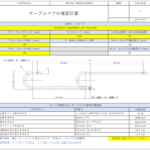
How to determine the length of cable bearers, number of links, and the dimensions of a clean installation, and the size of the opening
Today's note is about "how to determine the length, number of links, and crisp installation dimensions of cable bearers and aperture size. There are two basic things that the mechanical design side should pay attention to when selecting and installing cable bearers. &n ...
See more.
Optimal cable bear selection method based on calculations
Calculating the internal void to protect the appropriate storage rate
The storage ratio is an indicator of how much wiring can be packed into the internal space of a component. If wiring is crammed into a space with no space between the wires, the wires rub against each other violently with each bending movement, and the frictional heat causes the sheath to break prematurely.
For this reason,The absolute rule is to allow a reasonable amount of room for interior space. For general round electrical wiring, it is strongly recommended that the storage ratio to the interior cross-sectional area be kept generally below 60 percent. Furthermore, when storing pneumatic or hydraulic hoses, the phenomenon of the hoses themselves expanding and thickening when under pressure must be taken into account. Therefore,If hoses are included, more stringent standards must be established, and efforts must be made to keep storage rates as low as 40 percent to 50 percent or less.
As a specific calculation to determine the inner clearance dimensions, the total width of all the wires in a horizontal row is determined, and the required inner width is calculated by adding a clearance of at least 2 mm to the outside diameter of each, or at least 10 percent of the outside diameter. For the inside height, select a size from the catalog that meets the dimensions of the outside diameter of the thickest wiring with sufficient margin.
Bending radius that does not stress the cable
As mentioned earlier, as the components bend and move in a U-shape, the internal wiring is subjected to continuous bending stress. If this value is too small, the copper wire inside the wiring is subjected to excessive tensile and compressive stress, and this is the biggest cause of premature wire breakage due to metal fatigue.
When storing multiple types of wiring at the same time, the wiring with the highest value among the tolerances each has is used as the reference. And,Selection of cable bearers with a bending radius greater than the standard value is the basic principle for ensuring the longevity of the entire system.Never compromise the bend radius, even when space is limited.
Examples of allowable bending radii specified by the manufacturer
The specifications of each manufacturer that produces wiring always include the minimum allowable bending radius for use in a moving environment. As an example, the technical data for Oki Electric Cable's robot cable (https://www.okidensen.co.jp/jp/prod/cable/robot/orf.htmlIn the case of fixed section wiring, the value is 4 times or more than the cable O.D., while in the case of moving section wiring, the value is 6 times or more than the cable O.D. in the case of unshielded wiring, and 8 times or more than the cable O.D. in the case of shielded wiring.
When making a selection, be sure to directly check the specifications of the wiring manufacturer to be employed.
Logical use of dividers to prevent mixed distribution lines
Randomly mixing wires of completely different thickness and hardness in a single space is a breeding ground for trouble. For example, if a thick, heavy power line and a thin signal line are placed side by side as they are, the thick line rides on top of the thin line at the bend, locally crushing the sheath of the thin line by its weight and stiffness.
To prevent interference between these different types of wiring, partitions that physically divide the interior space are actively utilized. Vertical dividers can be used to completely separate the space as independent rooms on the left and right sides, ensuring that wiring does not come into direct contact with each other. The table below organizes the wiring combinations to be mixed and the effective countermeasures to be taken.
| Combinations and conditions of storage targets | Mechanical and electrical problems that may occur | Recommended use of dividers and measures |
| Mixture of cables with widely differing outer diameters | Thin wires underlie thicker, heavier wires, causing localized wear of the sheath due to friction and pressure. There are also concerns about noise interference. | Divide the room completely with separators. Maintain spacing to prevent thin cables from being undermined by thicker, heavier cables. |
| Heavy power lines and lightweight communication signal lines | If the weight is biased to one side, the carrier will twist during operation. | Power lines are placed on both sides of the carrier to equalize the load balance on both sides. Signal lines are placed in the center to prevent noise interference. |
| Mixture of electrical cables and pneumatic and hydraulic hoses | The hose expands and pulsates with each application of pressure, continually striking and wearing down adjacent electrical cables. | Be sure to strictly isolate with a separator. Ensure that the space on the hose side has sufficient clearance to allow for expansion due to pressure. |
| Reference source: JMACS Technical Guide (https://www.jmacs-j.co.jp/documents/tech/kadoubu.pdf) | ||
Cable placement to optimize internal space
When determining the internal layout, the most ideal condition is flat, with all wiring neatly arranged in horizontal rows. It is strictly prohibited to place wiring in multi-stacked arrangements just because there is space to spare.
This is because the weight of overlapping wires prevents the natural slipping motion of the wires when bending due to their mutual weight, and the tension loses its escape route, leading to wire breakage. Care must also be taken to balance the placement of wires. If heavy wiring is placed unevenly on one side, torsional forces act on the entire protective component, causing only one link to wear abnormally.
Heavy lines should be distributed to both ends as much as possible to equalize the weight balance between the left and right sides, while lighter lines should be placed in the center. Also,Although it may be tempting to neatly bundle and organize multiple wires, never tie them together with insulocks or other means at bends. When tied together, the slip to absorb the length difference is completely lost, causing a corkscrew phenomenon that deforms the entire wiring into a spiral, resulting in catastrophic damage.
How to select cable bearers to extend service life
Measures to relieve cable tension and prevent wire breakage
In moving parts, damage is most likely to accumulate at the root where the wiring is connected to the connector. At the boundary between the hard connector parts and the soft wiring sheath, stresses caused by vibration and bending can easily become extremely concentrated.
To alleviate this stress concentration, it is extremely effective to cover the connection with heat-shrinkable tubing or a special sleeve to provide physical support by smoothing out the change in rigidity. Careful attention must also be paid to adjusting the length of the wiring at the fixing points. If the wiring is set too short and taut when secured at both ends, the wiring itself will bear the tension when the protective component is fully extended to its maximum stroke, and the internal core wire will be immediately torn out. Conversely, if the wiring is set too long, the wiring will meander inside, causing severe friction with the inner walls of the protective element.
The key to achieving long life is to provide a natural margin that is neither too short nor too long, and to allow a slight degree of freedom for the wiring to move back and forth during bending.
Protective design for environmental resistance
It is also the designer's role to anticipate what environmental factors the facility will be exposed to and to develop protective measures to withstand them. A variety of foreign matter may be scattered in the factory, ranging from invisible microscopic dust particles to sharp metal fragments produced in the cutting process.
When these get inside, they act like a file that scrapes off the wiring sheathing.In such adverse environments, closed-type components with hermetically sealed structures are selected to physically shut out intrusion from the outside. However, being sealed presents a new challenge in that heat can easily build up inside.
When storing power lines that carry a large current, thermal countermeasures such as changing the conductor cross-sectional area of the wiring to one rank thicker are considered at the same time, taking into account the decrease in allowable current as the ambient temperature rises. On the other hand, manufacturing processes in a clean room do not allow even the slightest dust generated by the component itself. In this case, a linkless structure with no sliding parts or a low-dust-producing type product using low-wear materials should be specified, and a design that maintains a high level of cleanliness in the space is required.
Maintenance requirements to prevent problems
For equipment that is designed to operate continuously over a long period of time, how easy it is to perform daily visual inspections and periodic parts replacement directly affects life cycle costs.In order to properly manage the wear condition, it is recommended that the allowable wear of the links specified by the manufacturer and the deflection limit of the free span section be clearly stated in the instruction manual to clarify the maintenance criteria for the operator.
Absolute principle of simultaneous replacement in case of damage
There is a major principle that must be strictly adhered to in the field during operation. The strict rule is that if a link in the main body of a protective component is damaged or cracked, the wiring inside must also be replaced with a new one without exception.
In the process leading up to the breakage of the main unit, or at the moment it deviates from its track, the internal wiring is subjected to excessive tensile and bending stresses far beyond what is expected. This is because it is extremely likely that invisible and fatal metallic fatigue has accumulated in the ultra-fine copper wires inside, even if the coating is not damaged at all from the outside. If only the main unit is replaced to save cost, the wiring disconnection problem will reoccur immediately afterward, resulting in the equipment being shut down twice.
Highly accurate lifetime calculation derived from operating conditions
Before final design specifications are determined, a process is taken to logically verify that the envisioned components will reliably meet the required life of the equipment. Parameters such as the equipment's maximum travel speed, maximum acceleration, hours of operation per day, and number of operating days per year are sorted out to calculate the total expected travel distance and number of bends.
Many major manufacturers, such as Tsubakimoto Chain and THK, now offer advanced technical calculation tools on their websites that allow users to simply enter these operating conditions and automatically calculate equivalent loads and life correction factors to simulate expected life. For example,Tsubakimoto Chain's automatic cableveyor selection tool and others, it is possible to select parts on an engineering basis, without relying on experience and intuition.
If the calculated results are less than the required life of the equipment, we will optimize the design by increasing the component size to increase the allowable load or adjusting the operating speed parameters to ensure the target durability.
How to select cable bearers with caution
Application of machine safety standards defined by JIS standards
When designing equipment to be operated in Japan, it is a prerequisite that it meets the safety standards for machinery based on the Japanese Industrial Standards. In particular, the standards that address the safety of electrical equipment strictly stipulate items related to the physical protection of wiring in moving parts, the maintenance of proper bending radii, and even the relaxation of tension on the terminals.
In order to meet these standards, it is strongly required that unprotected designs that leave wiring exposed and trailing in the air be avoided, and that they be covered with appropriate protective enclosures. It is required to verify that the selected protective components have a robust structure that can securely hold the wiring itself while ensuring safety to the surrounding workers, and to build a safe equipment system in accordance with the spirit of the standard.
CE marking compliance required for export
When exporting developed automatic machines and robot systems to the European market or delivering them to major customers who demand global safety standards, conformance to CE marking is an unavoidable legal requirement. In order for the equipment as a whole to meet the strict requirements of the Machinery Directive and the Low Voltage Directive, the safety of all components used will be put to the test. Wiring and protective components that are integrated into the equipment and function as an integral part are comprehensively examined during the conformity assessment of the entire equipment.
However, ensuring that technical data and declarations of conformity provided by manufacturers are collected at the component procurement stage and that technical documentation is in place to prove the legitimacy of the design is a prerequisite for smooth customs clearance and export.
RoHS Trap to Be Aware of for Europe
It is also necessary to have a deep legal understanding of the RoHS Directive, an environmental regulation. In this directive, which restricts the use of certain hazardous substances in electrical and electronic equipment, there are pitfalls in legal interpretation that designers can easily fall into.
As mentioned above, if the product is shipped as integrated wiring inside the equipment, it is treated as part of the overall equipment compliance with the directive. However, the situation is completely different if the wiring assembly is sold or exported to a European customer as a stand-alone replacement part for future maintenance of the equipment, such as a wiring assembly with a special connector processed.
In this stand-alone case, the wiring assembly itself is regarded as an independent electrical/electronic device, and it is required to conform to the RoHS Directive as a component and to affix the CE marking accordingly. Therefore, it is necessary to make a proactive decision to select components that have been certified as compliant with the standard from the beginning in anticipation of future provision as maintenance parts.
Summary of reliable cable bear selection methods
The following is a summary of the important points and conclusions of the selection process that are useful in practice as explained in this article.
- Understand the difference in terminology and correctly use the generic name cable carrier in official drawings
- Understand and compare the technical areas of expertise of each manufacturer, such as Tsubakimoto Chain, Igus, THK, etc.
- Determine whether the product is made of lightweight plastic or robust metal, considering resistance to ambient dust, heat, etc.
- If a sealed environment is required, choose a closed type and take internal heat control measures as well.
- Check if the weight calculated from the stroke length is within the free span allowance in the catalog
- Always use special wear measures and guide rails together when sliding movements occur during long-distance travel.
- Calculate the exact number of lean links from the fixed end positions using a formula to optimize the length
- Design the interior space storage ratio to be a safety margin, usually no more than 60 percent.
- Size components based on the largest required bend radius of all wiring
- Logically divide the room with a divider when lines with different outside diameters and pulsating air hoses are mixed.
- Internal wiring should be laid flat, not stacked. Binding with insulocks should be avoided at all costs, as this can lead to wire breakage.
- The base of the connector is protected by a sleeve to provide enough room to release tension during operation
- When a part of the main unit is damaged, the internal wiring is replaced with new wiring at the same time to prevent serious wire breakage.
- Utilize life expectancy calculation tools available on each company's website and compare them to the required life of the equipment.
- Pay attention to individual CE marking and RoHS compliance when exporting individual maintenance parts to Europe.
That's it.