Today, we are going to discuss the "Design of LM guide mounting surface of THK (parallelism and supplementary information)Here is a note about "The
When using the LM Guide(Extracts from the THK catalog regarding the accuracy of the mounting surfaces to be designed, with additional notes from me on how to draw the mounting surfaces.I will do so.
Design of LM guide mounting surface
In this article,The following is an excerpt and supplemental information from the catalog regarding the "parallelism" of the LM Guide mounting surface.
The following information is not included in this article, please check the separate catalog.
- Example of arrangement of guide structure (combination of LM guide orientation, etc.)
- How to fix the LM Guide according to the conditions of use (application, vibration, etc.)
- Dimensions of the mounting surface (e.g., height of the mounting surface shoulder and radius of the chisel)
- Tolerance of perpendicularity of butt surface and dimension from butt surface to mounting hole, etc.
- Chamfer of mounting tap
- Regarding the LM Guide's own standards (indication of standards and combinations, etc.)
- Combination display of LM rail and LM block (joint use)
Parallelism tolerance of LM guide mounting surface
The LM Guide has its ownIt has the ability to self-adjust, but how far it can be tolerated depends on the model and skimmer (with or without pressurization)The LM guide is not designed to be used in the same way as the LM guide. In addition, the design must reflect these errors in the geometric tolerances of the drawings of the parts to which the LM guide is to be attached, since errors in the mounting surface of the LM guide will affect its life.
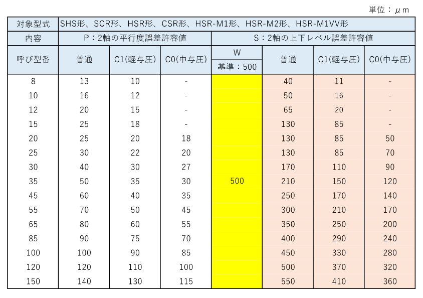
The following is an excerpt from the commonly used (SHS, SCR, HSR, CSR, HSR-M1, HSR-M2, and HSR-M1VV types).
Parallelism error tolerance of the two axes [P] andAllowable vertical level error of 2 axes 【S】.
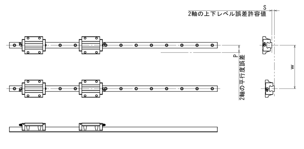
In general useParallelism error tolerance of 2 axes (P)andAllowable vertical level error for 2 axes (S)are as follows *The upper and lower level tolerances here are based on an inter-axial distance of 500 mm in general use and are proportional to the inter-axial distance.
Supplement] Accuracy and Machining of LM Guide Mounting Surface
Supplementary information starts here. It should be noted that the parallelism error tolerance and vertical level error tolerance of the LM guide mounting surface are as follows,This is only a requirement for the operation of the LM Guide and does not mean that the accuracy of the unit using the LM Guide is guaranteed.
For the accuracy of the unit, the accuracy of the parts on which the LM guide is placed,In particular, the posture of the mounting surface is very important. For example, just as grinding can produce a flatter surface than cutting,It is important to design the polishing process to be able to grind according to the situation.That is what I mean. Of course, I don't think it is necessary to polish everything and it is a case by case basis.
Polishing of LM guide mounting surface
Please refer to TechNote for more information on flat grinding work. It is wonderfully comprehensive. (Fundamentals of Grinding Process:https://www.ipros.jp/technote/basic-grinding/)If the accuracy of the LM guide mounting surface (accuracy as a unit) is to be achieved through this polishing process, the shape should be such that it can be polished. Such a design makes it easier to deal with accuracy problems and to respond to them after the drawings are submitted.
Example: Violet Shape Indication Method
According to the LM Guide Catalog "Key Design Considerations", the radius of the shoulder of the mounting surface should be R. However, this is suitable for machining, and if polishing is assumed, the shape should be such that it can be "nipped". (Image)
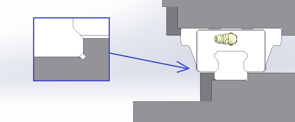
In my case, I do not give dimensional instructions for the nigue portion here. If necessary, I would check with the processing manufacturer each time, but I describe it as an arbitrary shape on the drawing.
Supplement: Why polishing nige is necessary
As a supplement, why do you need a polishing nige and what is the shape?
Quote: From Wisdom.
The corners of the grinding wheel (the boundary line between the periphery and the sides) are always R-shaped. Therefore, the corner of the workpiece becomes R-shaped. To avoid this, the grinding nibs are attached so that the R part of the grinding wheel does not touch the workpiece.
The following is the reason for this. In the polishing niger, the shape follows the excessive part of the grinding wheel, so it is not possible to specify the shape of the Sumi-R. This is the reason for this nibble.
Accuracy of LM Guide mounting surface (download)
The tolerance for vertical level error (S) for two axes is based on the distance of 500 mm between axes and is proportional to the distance between axes, so that the tolerance can be calculated if it is inserted in the yellow section.
That's it.
-

-
Load and life calculation for LM Guide / Linear Guide
This section summarizes various calculations and concepts related to the load and life calculation of LM guides/linear guides used in machines. Calculation LM Guide Load Calculation Vertical Conveyance (2 rails, 2 blocks) Horizontal Conveyance (2 ...
See more.
