Today, we are going to discuss the "There are three main reasons/causes for poor LM Guide movementThis is a note about the "LM Guide". Some time ago, during the post-assembly/adjustment work of a certain machine, I saw an LM guide that was not moving properly.
To be more specific about the poor movement, the machine should do 250st, but it stops with about 5st left, and if you push it by hand, it moves to the end. In other words,The fact that the thrust of the air cylinder, which was supposed to drive the LM guide with sufficient margin, was not enough to drive the LM guide.will be.
The reason for the poor movement of the LM guide was that the LM guide was not installed correctly. The structure of the incorrectly installed LM guide is shown below, and it was installed using a knock pin for positioning. (Image is for reference only)
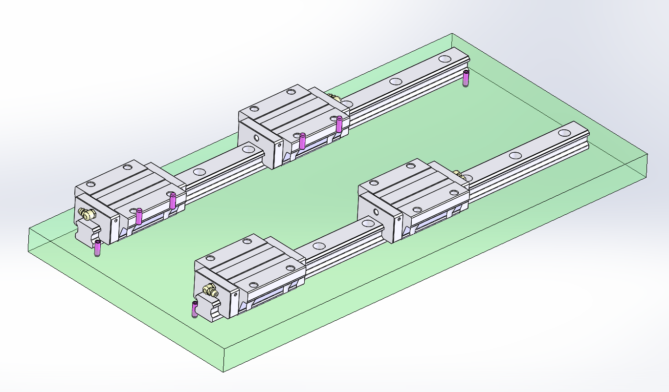
I am sure that there are equipment manufacturers who use this type of positioning. In the past, when I saw a design that used this type of positioning, I said to myself, "It's OK to use this type of positioning in rough areas. I saw a design with this type of positioning in the past, and I thought, "Okay, let's do it (take a crack at it)," although I had temporarily adopted it,On second thought, there's a good chance it could be a bad situation.So I haven't done it recently.
Causes of poor LM Guide movement
Then,Three causes of poor LM guide movementbullet points.
- LM Guide standards are not correct.
- Poor installation of LM guide
- The design does not allow for proper installation of the LM guide.
And so on. We will now explain those details.
No. 1: The LM Guide does not meet the criteria.
The LM Guide itself has a reference plane. ThisIf the reference plane is wrong, it may not work properly = poor movement.
Reference side and driven side LM guide reference plane (for THK)
For example, when two axes are installed in the same plane in an LM guide that requires parallel or higher accuracy, there will be two LM guide assemblies. TheOne side is the reference LM guide and the other side is the driven LM guideAlthough it will be,The differences are as follows
 (Borrowed from THK)
- Reference LM rail:KB" is stamped at the end of serial number.
- LM rail to be driven:No "KB" at the end of serial number
*Normal class has no instructions, so either is acceptable.
Further,The blocks and rails of the reference and driven LM guide assemblies themselves also have reference surfaces.
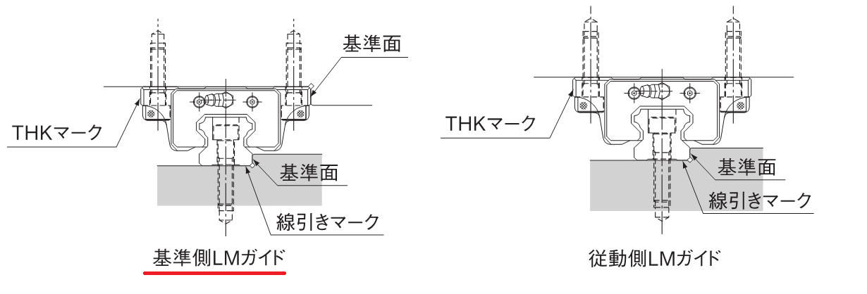
(Borrowed from THK)
- Reference side (with "KB" at the end)LMWBLOCKTo:The other side of the THK mark is the reference plane... is considered to ...
- Reference side (with "KB" at the end)LM RailTo:Line mark side
The following is an indication of the non-standard driven side
- Driven side (without "KB" at the end)LMWBLOCKTo:No reference plane
- Driven side (without "KB" at the end)LM Railto: line-drawing mark side is the reference
Why is there no reference plane on the block but on the LM rail of the driven LM guide assembly?To fix LM rail and use LM block freeIt is.Thus, the reference is considered to be the opposite of the standard, which leads to a decrease in accuracy and worsening of the condition of the movement.
No. 2: Poor installation of LM guide
Although there is a proper installation method for the LM Guide,Incorrect installation will result in poor movement of the LM guide.
Installation order of LM Guide
The order of installation of the LM Guide is as follows
- Butt the reference side (line drawing mark side) of the LM rail
- Adhere (push) the LM rail with a push bolt (or plate, etc.)
- Butt the reference side (opposite side of the THK mark) of the LM block
- Adhere (press) the LM block with a push bolt (or plate, etc.)
*If there is no push bolt or push plate, it can be fixed by pressing it with a small vise or the like,this (something or someone close to the speaker (including the speaker), or ideas expressed by the speaker)If the order and installation is not proper, the LM rails will be "c" shaped, and the resistance will be tighter in the middle, resulting in poor operation.
If you do not or cannot fix it by butting against it.
If it is not or cannot be fixed by butting it, the following methods are available
- A method of gradually moving from temporary tightening to full tightening while running
⇒ From the Opportunity Assembly Room:Parallelization of the driven side of the LM guide - How to use eccentric clamp bolts
⇒Recommendation for rail fixing of LM Guide and Linear Guide
The problem of LM guide installation with knock pins, as explained at the beginning of this article, is
- It was a structure that could not be pressed against.
- Difficult to install because it could not be pressed against the wall, and it ended up being installed in a "C" shape.
This was the reason.
No.3: The design does not allow for proper installation of the LM guide.
This is where the designer must be especially careful. If the design makes it impossible to do #1 and #2, it is no wonder that the LM guide does not work well.Conversely, if the design satisfies the above two conditions, it is easy to make the LM guide depend on the machine accuracy of the processing machine = the catalog capacity of the LM guide.
The seriousness of poor LM guide movement is that the drive capacity may be insufficient depending on the condition of the LM guide installation.Failures that occur when the LM guide is not properly installed and the result is poor movement are
- Operation speed is slowed down.
- If it's bad, the movement stops in the middle.
If this is the case, the result isIt increases the power of the drive. There's also the possibility of making wrong improvements such as
This is a bit off topic, but the coefficient of friction of the LM Guide is 0.001 to 0.003, which, when calculated normally, means that even a fairly heavy object can be pushed with little force. In reality, however, I think that in most cases, more force is required than calculated.This is partly due to the resistance of the grease and partly due to the presence or absence of pressurization, but there must be no loss due to the installation method in order to satisfy the pushing force planned in the design.Of course, the fact that some error can be absorbed is another selling point of the LM guide, but even if some error = error, it does not mean that the guide is driven almost without resistance.
Therefore, it is important to design the product, including the surrounding area, for correct installation.
- Allow space for proper installation or
- If space is difficult to secure, subunits can be made available for assembly.
Please consider that the catalog spec movement is finally possible when these are done.
That's it.
-

-
Load and life calculation for LM Guide / Linear Guide
This section summarizes various calculations and concepts related to the load and life calculation of LM guides/linear guides used in machines. Calculation LM Guide Load Calculation Vertical Conveyance (2 rails, 2 blocks) Horizontal Conveyance (2 ...
See more.
