Today, we are going to discuss the "How to create a going/returning cable bear model in SolidWorksHere is a note about "The
I am working on a design job at SolidWorks,Cable bearers are the most troublesome part of model making. I think it is.In particular, the following are reasons why modeling cable bearers in 3D CAD is troublesome.
- It doesn't work as downloaded.
- Need to create a forward/backward movement.
- Wondering what to do with the parts representation power (and wondering how others around me are doing it)
The reason you can't use it as downloaded is...How to determine cable bear length, number of links, and neat installation dimensions As mentioned above, this is because the mounting height must be increased from the basic shape. The downloaded file has to be rebuilt each time.
For this cable bear, it is necessary to create a back-and-forth motion to check for interference. Although there are more and more places that do not use assembly drawings nowadays, it is still necessary to create a model that allows checking the back-and-forth motion.
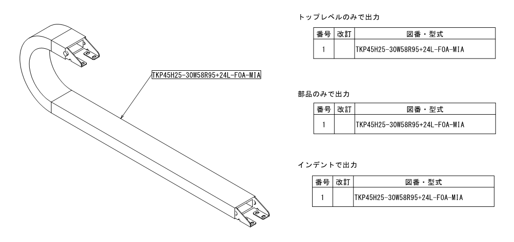
Finally.Wondering what to do with the BOM This is the part called "BOM". In SolidWorks, there are three BOM types that can be used to output a BOM from a model you have created.
(1) Top level only
Shows the parts and subassemblies in the tree of that assembly, but not the individual parts that make up the subassembly
*Tree building is important because the structure of the tree affects the BOM.
(2) Parts only
Subassemblies are disassembled and subassembly components are displayed as individual items
*Even if the tree configuration is messed up, if the parts are in it, you can pick them up reliably (I do this basically).
(iii) Indentation
The parts and subassemblies in the tree of that assembly are displayed, as well as the individual parts that make up the subassembly.
*The appearance is very easy to understand and makes a careful bill of materials, it's just a little difficult to handle subassemblies.
The bottleneck here is that cable bearers need to create front-back motion, but how to express that, and how to create a model that will appear in the parts list regardless of whether the model has front-back motion or not....
Today, I would like to share with you how to make a cable bear model, which I have incorporated into many different ways of doing things. Please check out the video below to see the finished product. This is creating two movements in one assembly.
- Cable Bear Modeling Procedure
- (1) Download the cable bear to be used.
- (2) Open the cable bear assembly model and delete the link section.
- Basic model inserted in place of (3) link section
- (4) Create configurations before and after operation
- In addition: This is what it looks like in the parts list
- Finally: Download data for the link body
Cable Bear Modeling Procedure
Let me start by making some notes. In creating this model, I will be using Tsubakimoto's TKP series.
Tentative selection criteria
- Stroke used: 1250
- Full stroke: 1350 (stroke that moves due to structure)
- Cable bear: TKP45H25 (made by Tsubakimoto)
(1) Download the cable bear to be used.

- I am downloading by full stroke minutes, not by strokes used
- The model is a SolidWorks model (SolidWorks >=2006)
(2) Open the cable bear assembly model and delete the link section.
- Open the assembly model of the cable bear and delete the link section (body section).
- Fixed parts remain fixed, movable parts are unfixed
- Exclude from BOM
- Match moving parts (front and flat)
- At this time, raise the height 10 to 15 mm (arbitrary value) to match, taking the mounting height into consideration.
Basic model inserted in place of (3) link section
- Bring in pack-and-go from standard parts
- Modified the model of the link section for this project (using calculation sheet and catalog)
↑upThe above two are not in the video.
- Inserted link part matches fixed side, movable part mounting matches link body
(4) Create configurations before and after operation
- Create a configuration for pre- and post-operation in the assembly itself
In addition: This is what it looks like in the parts list
The model created in the above work is shown below when it is created with three patterns of BOMs. The model created here will have the same representation even if the configuration is changed, so changing the model representation in the assembly diagram will have no effect.
Finally: Download data for the link body
Finally, I would like to share the data of the link body, but I am very sorry. I have decided to charge a fee (500 yen) for this time because it is a CAD model and I believe it is the best modeling I have done after many years of experimentation.
Please read and accept the following precautions before downloading.
Confirmation 2: Downloadable data is for SolidWorks 2018.
Confirmation 3: Video instructions are included for handling and modifying the body model.
Confirmation #4: Please do not distribute the information in a secondary manner.
Confirmation 5: Basically, we cannot accept returns after downloading.
Where to download:Mechanical design memo (fee-based data sales)
Please refer to the above if you are in need.
RELATED:Solidworks
RELATED:Cable bear