Here."From the principle of positioning in machine design to different positioning methods according to accuracy." Note the
In machine design, positioning is an extremely important process that determines the performance, quality, and cost of a product. However, it is also a very important process that determines the performance, quality, and cost of the product,The methods and principles vary widely, and extensive knowledge is required to make the best choice. We believe that many of you have faced challenges in the design process, such as "Couldn't we have done it better?" or "Why can't we be more accurate?
In this article, we will discuss the subject of positioning, from the underlying principles, to specific methods, to proposed configurations of jigs to achieve high precision, and even to the selection of the type of jig according to the desired precision, and the information that machine designers should know.Comprehensive explanationThe course is designed to provide students with a new perspective on their design work. The goal of this course is to provide a new perspective on design work while systematically understanding the overall picture of positioning, with practical knowledge and cautions as well as theory.
- Positioning Principle underlying the design
- Finding a method for high-precision positioning
- Positioning used in assembly Type
- Positioning jig on the machining shop floor
- Advanced positioning Accuracy and technology
Positioning Principle underlying the design
Positioning" in machine design is not simply the act of placing parts. It is to assure the function and precision that the machine should have,The most fundamental design concept andIt can be said. This section describes the basic principles that serve as the foundation for all positioning. This knowledge will serve as a compass for more advanced and rational design.
The concept of 6 degrees of freedom that defines space
To understand positioning, it is essential to first understand the concept of "6 degrees of freedom. An object placed in space can translate (move) in three directions (back and forth, left and right, and up and down) and rotate in three directions around its respective axis, for a total of six independent movements. This is called six degrees of freedom (6-DoF).
Let me put it this way,Positioning is the act of intentionally constraining these six degrees of freedom one by oneIt is nothing more than a For example,Fixing a part completely means the same as constraining all six degrees of freedomThe result will be the same as the above. On the other hand, if you want to have only a specific rotational motion, as in a bearing, you are constraining 5 degrees of freedom other than that motion.
For this reason, the designer must be clearly aware of which degrees of freedom to allow and which to constrain.
The 3-2-1 Principle for Strict Constraints
So what exactly should be done to constrain the 6 degrees of freedom without excess or deficiency? The mostThe basic, universal method is the "3-2-1 Principle."It is. This illustrates the principle of stabilizing an object at a minimum of six points.
First,Three points support the bottom (main reference plane)The first two rotations are then applied to the second one. This constrains vertical movement and forward/backward and left/right tilt (two rotations). Next,Two points support the side (sub-reference plane)This will suppress left-right movement and horizontal rotation. And finally,One remaining point supports the front surface (third reference plane)and restrains forward and backward movement.
Thus, by supporting the object at a total of six points (3+2+1), the object's six degrees of freedom are completely constrained. This principle is applied in various situations, such as when fixturing a workpiece with a machining jig, to enable highly repeatable and stable positioning, even if the surface of the workpiece is not perfectly flat.
-

-
The theory of the positioning method, "The Rule of 3, 2, 1."
Here we note one of the theories to be held in the Complete Guide to Positioning, the "Rule of 3, 2, 1," which is the basis of how to position a plate (square) member. This is the ...
See more.

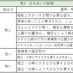
Method selection according to the condition of the positioning surface
As mentioned above,The 3-2-1 principle is based on "point" support, but in practice, the best method of contact depends on the condition of the surface of the part to be positioned. Choosing a positioning method without considering the material and surface conditions of the part can result in inaccuracy or damage to the part.
Highly flat and hard surfaces (e.g., ground surfaces)
For hard surfaces such as hardened steel with high flatness, "point contact" provides the highest repeatability. Receiving with a hardened pin tip or ball makes the contact point clear and minimizes the effects of microscopic dust and oil film.
General machined surfaces (e.g. milling surfaces)
For general flat surfaces, such as those obtained by milling, "face perpendicular" is also a valid option. Receiving on a surface expands the contact area, resulting in high rigidity and load capacity. However, since there is a risk of accuracy degradation due to surface undulation and dust entrapment, a clean environment and a certain degree of flatness are prerequisites.
Rough and uneven surfaces (cast surface, black skin, etc.)
If the surface is rough and not flat, such as the surface of a casting (cast skin) or the black skin of a forging, "surface contact" should never be performed. Because you don't know where the contact is made and it is not stable at all.It is.
In such cases, it is effective to use a pointed screw or a jagged clamp called a "devil's claw" for positioning by piercing. This allows stable 3-point support, etc., even on uneven surfaces.
Soft and easily scratched surfaces (aluminum, resin, etc.)
When "point contact" is applied to parts made of soft materials such as aluminum, resin, or painted surfaces, the contact pressure (surface pressure) becomes too high, resulting in indentation.The surface pressure is then reduced by using a "face contact" with a large contact area or a wide block. In such cases, it is important to reduce the surface pressure and prevent damage to the parts by daring to use a "face contact" with a large contact area or a wide block to receive the parts.
Kinematic Design and Elastic Averaging
Two contrasting design philosophies exist for positioning in mechanical design: how to deal with imperfect realities (e.g., manufacturing public - thermal deformation).
Kinematic Design (Strict Constraints)
Kinematic design is a design concept that aims to constrain the 6 degrees of freedom of an object at exactly 6 contact points without excess or deficiency This approach avoids in principle the occurrence of internal stresses due to manufacturing errors and thermal expansion and ensures extremely high repeatability. This approach in principle avoids internal stresses caused by manufacturing errors and thermal expansion and ensures extremely high reproducibility.
Products that embody this principle are "kinematic couplings" and "kinematic mounts. They strictly constrain the 6 degrees of freedom by skillfully combining elements such as spheres and V-grooves, and spheres and planes. For example, three V-grooves are placed at 120 degrees each, and a sphere is placed in contact with each to achieve highly repeatable positioning.
Such mechanisms have become indispensable technology in fields such as semiconductor manufacturing equipment and optical measuring instruments, where accuracy in the micron range or even lower is required. THK Precision Co., Ltd. and other manufacturers have applied this principle to the development of high-precision "Precision Stage Seriesand "piezostageThe company offers a "one-stop shopping" service for all of its customers.
Elastic averaging (over-constraints)
On the other hand,Elastic averaging is a design concept that intentionally uses a large number of contact points, well in excess of 6 points, to constrain the component The contact points are then averaged together to obtain a stable overall positioning. This approach uses the elastic deformation of the material to "average out" the positioning errors at the individual contact points, resulting in more stable overall positioning.
Products representative of this philosophy are "Haas couplings" and "curvic couplings. They are machined with precision serrated teeth (serrations) that radiate around the circumference, and when two parts are engaged, they make contact at a very large number of points. Even though there may be minute errors in the position of individual teeth, the large number of interlocking teeth averages out the errors, resulting in extremely high rigidity and positioning accuracy overall.
Nikken Kosakusho Co. and ... andIZUSHI Corporation (Izushi)and others manufacture high-precision indexing tables using these couplings, which are widely used in machine tool swivel tables and other applications.
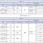
| special characteristic | Kinematic Design (Strict Constraints) | Elastic averaging (over-constraints) |
| basic principle | Constrain the 6 degrees of freedom at exactly 6 contact points | Averages errors over a large number of contact points (over-constraints) |
| reproducibility | Very high | Lower than kinematic design, but good |
| rigidity | relatively low | Very high |
| load bearing capacity | relatively low | Very high |
| Tolerance and resistance to thermal deformation | High (less likely to generate internal stress) | High (elastic deformation absorbs) |
| Typical Applications | Optical instruments, precision measuring instruments, space equipment | Machine tool couplings, heavy-duty jigs |
High stiffness brought about by over-constraints
As mentioned above,The elastic averaging concept intentionally creates a state of "over-constraint". This is a method of supporting and securing a component at a number of points well in excess of the six points required to constrain six degrees of freedom.
The reason for the excessive restraint is that it provides extremely high stiffness. When a load is applied,The force is distributed over a number of contact points. This reduces the force applied to each individual contact point and minimizes deformation of the entire partThe first is the
However, this design requires caution. If the positional accuracy of each contact point is poor, simply assembling the parts may cause high internal stresses in the parts, leading to distortion and breakage. Therefore,If over-constraints are employed, high machining accuracy of each part is a prerequisite, or the design must skillfully utilize elastic deformation of the material to relieve stress.
Finding a method for high-precision positioning
Having understood the basic principles of positioning, the next thing to look at is,How to achieve "high precisionThis is the specific methodology that we use. In this section, we will delve into the principles and concepts that designers must know in their pursuit of accuracy. Incorporating these concepts into your designs will dramatically improve the quality of your products.
Abbe's principle that determines accuracy
Abbe's principle" is an inescapable part of the discussion of high-precision positioning and measurement. This is an extremely important guideline to minimize measurement error.
This principle simply states that the object to be measured and the scale used to measure it must be placed in a straight line in the direction in which the measurement is to be made If the object to be measured is out of alignment with the scale, a slight tilt in the measurement will result in a large measurement error called the Abbe error. If the object to be measured is misaligned with the scale, a slight tilt in the measurement will result in a large measurement error called the "Abbe error.
This is why micrometers are in principle more accurate than calipers. This is not only true for measuring instruments. When designing a high-precision positioning stage, the key to achieving the target accuracy is to arrange the sensor (scale) that controls the movement and the point of action (object to be measured) that you actually want to move according to this principle.
Abbe's Principle" is explained in detail with illustrations and concrete examples in the following pages.
- Keyence Corporation Measuring Instrument Navigator
https://www.keyence.co.jp/ss/products/measure-sys/measurement-selection/basic/abbe-principle.jsp - CMM-GUIDE CMM Japan K.K.
https://www.cmm-guide.com/column/abbes-principle.html - d-monoweb Explanatory site for manufacturing and design
https://d-monoweb.com/expert_column/what-abbes-principle/
Bryan's principle for dealing with angular errors
Bryan's principle can be thought of as a further development of Abbe's principle. While Abbe's principle deals primarily with linear errors, Bryan's principle deals with how small angular errors (pitch, yaw, and roll) that occur as the machine moves affect the measurement results.
For example, when a machine tool table moves, it may appear to be perfectly straight, but at the micron level it is moving with a slight tilt. If the measurement probe is positioned too far from the point of action (e.g., the tool tip), the table tilt will be magnified as a measurement error.
In ultra-precision positioning devices that require the ultimate in precision, advanced control is performed based on Bryan's principle to simultaneously measure not only the linear position but also the angular error associated with movement and compensate in real time.
The following academic papers and technical explanation pages describe the "Bryan Principle" in detail.
- Annals of the Faculty of Engineering Hunedoara (Academic Paper)
https://www.ajme.ro/PDF_AJME_2024_1/L1.pdf - Dutch Society for Precision Engineering
https://www.dspe.nl/knowledge/dppm-cases/high-precision-3d-coordinate-measuring-machine-according-to-abbe-and-bryan-principle/
Selection of a reference plane as a starting point for the design
A reference plane is literally a surface, point, or line that serves as a "reference" for positioning. Since the accuracy of the entire product is greatly affected by which part is selected as the standard, its selection is an important decision that should be made at the earliest stage of the design process.
In general, the reference plane is set to the surface that is most important to the function of the product and requires the highest accuracy. Positioning methods include "surface contact," in which flat surfaces make contact with each other, and "point contact," in which a point, such as the tip of a sphere, is used for positioning.
As mentioned above,The "face contact" is simple in construction and can withstand high forces, but it is vulnerable to slight distortion of the face and to dust entrapment. On the other hand, the "point contact" method provides more reproducible and stable positioning because the contact point is well-defined.
Thus, there are advantages and disadvantages in the selection of a single reference plane, and the most appropriate one should be selected according to the processing method and required accuracy.
What is a design that guarantees repeatability?
Repeatability is a measure of the degree of variation in returning to the same position when the same operation is repeated. The ability to maintain the same position every time, even when reassembling a disassembled machine or changing a jig on an automated line, is extremely important to ensure consistent product quality.
To guarantee this repeatability, several design considerations are necessary. For example, the aforementioned kinematic design is a design concept that theoretically achieves high repeatability. In addition, Imao Corporation's "flex locatorThere are also commercially available parts like the "M" that use a tapered shape to ensure the same position at all times without rattling.
In addition, Kosmek's "Expansion positioning pinThe "M" technology changes the diameter of the pin with air pressure to achieve zero clearance between the pin and the hole, thereby achieving high repeatability on the micron level. These technologies are essential for maintaining consistent quality, especially in automated production lines, without having to make adjustments at every setup change.
Positioning used in assembly Type
From here, in assembling the machine,Specific machine elements used to determine the relative position of parts and componentsThe following is an explanation of the following. Although they may appear to be simple shapes, each has a distinct role and design point. Appropriate use of these elements is the first step in creating a highly accurate product.
Basic knock pin and diamond-shaped pin
The knock pin is the most widely used mechanical element for the purpose of precisely positioning two or more parts relative to each other when assembling them It is. Often used in conjunction with fastening bolts.
Combination of knock pin (round pin) and diamond-shaped pin
When positioning with two round pins, if there is a machining error in the distance between the two holes, the pins may not fit smoothly,This can cause problems with stress on the parts during assembly. A very effective solution is to use one round pin and the other "diamond-shaped pin". The first is
The rhombic pin constrains the position in one direction, but allows freedom in the other direction. This means that even if there is a slight variation in the center distance between two holes, the rhombic pin absorbs the misalignment, allowing for smooth assembly.
However, there are some caveats to this method. Since the orientation of the diamond-shaped pin is important, a method to fix the orientation, such as a keyway to prevent rotation during press-fitting, must also be considered.
Utilization of oval holes
Another solution is to keep both pins as round pins, but make one of the holes in the mating part a round hole and the other an "oval hole (long hole)". The same function can be provided to absorb machining errors in one direction as with the rhombic pin. Like the diamond-shaped pin, this pin can also absorb machining errors in one direction.
The advantage of this method is that it does not require special components such as diamond-shaped pins, and there is no need to worry about orientation. On the other hand,Machining oval holes can be more costly than machining round holes, so it is essential to select the best method depending on the production volume and required accuracy The first is
-

-
Design method for using knock pins and parallel pins as positioning
Here is a note on "How to design when using knock pins and parallel pins for positioning" mentioned in the "Complete Guide to Positioning". First, there are two major types of positioning for mechanical parts ...
See more.
Positioning by bosses with integral molding
A boss is a cylindrical projection on one part that fits into a hole in the other part for positioning. Bosses are used especially in injection molded plastic products and cast products such as aluminum die castings.
The greatest advantage of this method is that the boss is integrated with the part, eliminating the need for a separate part like a knock pin, leading to a reduction in the number of parts and costs. Many products around us, such as battery covers for remote controls and housings for home appliances, utilize this boss positioning method.
Tolerance control between the outside diameter of the boss and the inside diameter of the hole is an important design consideration. If the fit is too loose, it may cause rattling. On the other hand, if the fit is too tight, assembly may be difficult or the product may be damaged by excessive force. Appropriate tolerances must be set in consideration of the required positioning accuracy, as well as the characteristics and shrinkage rate of the molding material.
Spline that also serves as torque transmission
A spline is a shaft with multiple keyway-like concavoconvexities on its surface, and is mainly used to transmit rotational force (transmit torque) to parts such as gears and pulleys. However,Splines play an important role in torque transmission as well as positioning in the rotational direction.
Compared to a "key" that has only one keyway, a "key" is characterized by its ability to transmit greater torque because it engages with a large number of teeth. They are also classified into several types according to the shape of the teeth.
- Spline: The cross-section of the teeth has a shape similar to a square. Splines are often used in places where torque must be transmitted while sliding in the axial direction, such as in the drive shafts of automobiles.
- Serration: The cross-section of the teeth is nearly triangular in shape. The teeth are finer and have less backlash than splines, making them suitable for more precise fixation of the rotational position.
It is important to include these elements in the design options, not only as components that transmit torque, but also as positioning elements in the direction of rotation.
The relationship between the hole and the axis is determined by the relationship between the hole and the axis.
Mesh fit" is a term used to describe the relationship between the dimensions of a "shaft" and a "hole" in a component when the "shaft" is inserted into the "hole". . Depending on how this relationship is set up, the function of a part after it is assembled can vary greatly.
There are three main types of mating.
- Clearance: The shaft is slightly thinner than the hole, creating a "gap" between the two. This is used where the shaft needs to rotate or slide smoothly in the hole.
- Clamping: The shaft is slightly thicker than the hole, and pressure must be applied to engage. Once fitted, it cannot be easily pulled out. It is used in places where strong clamping force is required, such as bearing fixtures.
- Intermediate fit: A fit that is intermediate between a clearance and a tight fit. It is chosen at a point where it is possible to disassemble while maintaining accurate positioning, for example, by using knock pins.
The type of fit to be selected is an extremely important design consideration that is determined by the overall assessment of the function required of the part, the frequency of assembly and disassembly, and the cost.
-
-
About fitting (Tolerance table)
This section is a memo about fits, which are expressed together with dimensions in mechanical drawings. Basic information about fits and the fit tolerances that apply to commonly used parallel pins and bearings are summarized. Fits ...
See more.
Positioning jig on the machining shop floor
The principles of positioning are redefined in the context of the manufacturing workplace, and specific methods for accurately and firmly securing the workpiece (workpiece to be machined) to the machine tool are explained. Jigs and fixtures are the very place where positioning technology is put into practice, and their selection and use determine the quality of the product.
Jigs and clamps to fix workpieces
Jig is a generic term for auxiliary tools used to make operations such as machining and assembling parts easier, faster, and more accurate.It is. By utilizing jigs, it is possible to produce products of consistent quality regardless of who is working on them, without relying on the skill level of the operator.
Difference between jigs and fixtures
Originally,Jigs are strictly classified according to their function. For example, a jig is a tool that guides a drill blade to the correct position during drilling, while a fixture is a tool that simply holds a part in place. However, in modern manufacturing sites, especially those dominated by NC machine tools, these are generally referred to collectively as "jigs.
Separation of positioning and clamping
One of the most important principles in fixture design is to clearly separate the roles of "positioning" and "clamping. Positioning should be done by pins or reference surfaces, and clamps should play only the role of "holding" to maintain the position. Attempting to position with clamping force will deform the part and compromise accuracy.
Vise essential for milling
A vise is a basic fixture in milling and drilling operations that clamps and holds a workpiece between two clamps.
Vise Type
Vices come in a variety of types, depending on the application.
- Precision machine vices: Standard vices for milling operations, guaranteeing high parallelism and squareness.
- Milling Vises: Heavy-duty vise designed with high rigidity and strong clamping force to withstand high cutting forces during roughing.
- Hydraulic vise: High and reproducible clamping force can be obtained using hydraulic pressure, making it suitable for use on production lines.
Importance of "anti-lift function
One of the biggest enemies of accuracy in vices is the "lifting" phenomenon, in which the movable end of the vise lifts slightly during tightening and tilts the workpiece.. is . High-quality precision vises incorporate a mechanism to prevent this lifting.
This mechanism converts part of the clamping force into a downward force that strongly presses the workpiece against the bottom of the vise, ensuring accurate positioning. The availability of this function is an extremely important factor in vise selection for precision machining.
Chucks and collet chucks used on lathes
The chuck is a part that grips the material to be machined (workpiece) and rotates it with the spindle, mainly in lathe turning operations. Its most important function is to hold the workpiece at the exact center and with a firm force that will not be defeated by cutting forces.
Type of chuck
The most widely used "three-jaw scroll chuck" has the advantage of extremely fast setup because the three jaws move in tandem, but its repeatability is moderate. On the other hand, the "three-jaw scroll chuck" has a medium level of repeatability,The "Four Jaw Independent Chuck" requires time and skill to set up because the four jaws are adjusted individually, but it can grip square and irregularly shaped workpieces and can perform centering with extremely high accuracy.
Collet Chuck
The collet chuck pushes and pulls a split cylindrical part (collet) in the axial direction to grip the workpiece uniformly from all circumference by utilizing its elastic deformation.The large contact area prevents damage to the workpiece surface and provides extremely high coaxiality (runout accuracy) and repeatability. Suitable for precision machining of small diameter parts and continuous production from bar material.
Important guide pins and interlocks in molds
Positioning in injection molds and press molds requires extremely high precision to protect the expensive molds themselves from damage and to guarantee the quality of the molded product.
Guide pin and guide bushing
Guide pins are the primary mechanism for precisely aligning the stationary and movable sides of a mold. A thick, hardened guide pin planted in one side of the mold mates with a precision guide bush embedded in the other side of the mold to move the mold from rough to precise positioning during the mold closing process. Clearance management between the pin and bushing determines the accuracy of the mold.
interlock
Interlocks are tapered or square-shaped blocks that fit together on the parting line (mold dividing surface) just before the mold is completely closed. They have the important role of rigidly holding the mold in its final position against the enormous pressure (e.g., injection pressure) generated during molding and reducing the load on the guide pins.
Advanced positioning Accuracy and technology
Finally, we will discuss more advanced positioning techniques and ideas for improving design quality itself.
V-block for fixing cylindrical objects
The V-block is useful for stable positioning of cylindrical workpieces such as round bars and pipes. As the name implies, these blocks are machined with V-shaped grooves and are widely used in measurement and processing.
The V-shaped groove supports the cylinder with two tangent lines, preventing the workpiece from rolling and enabling the center line to be accurately defined. It is also used as a jig to hold a workpiece during marking or drilling, or as a holding stand when measuring shaft centering with a dial gauge. Normally, a set of two is used to stabilize a long cylindrical workpiece.
However, the accuracy of the V-groove of the V-block itself directly affects the positioning accuracy of the workpiece. Also,Since repeated use causes wear on the contact surface, it is important to select a hardened material with low wear resistance, especially when used for precision measurements, and to separate use for work and measurement purposes. The number of the
Zero point system to revolutionize setup
The Zero Point System is a positioning and clamping system that has dramatically revolutionized recent setup operations at manufacturing sites, especially machining centers. The system makes it possible to change pallets on which jigs or workpieces to be machined are mounted with a single touch and with extremely high repeatability.
This system consists of a clamping unit installed on the table side of the machine and dedicated nipples (pins) mounted on the pallet side. There are three types of nipples: locating pins, which determine the reference position; diamond pins, which stop rotation; and clamping pins, which only clamp (retract),The combination of these two features simultaneously ensures secure positioning and strong fixation based on the 3-2-1 principle. I will do so.
Stark" series by Lohmheld Halderand Nabeya's "Q-LockThese products are well-known for their extremely high precision, with repeatability of 5 μm (0.005 mm) or less.Although an initial investment is required to introduce the system, it is extremely effective in high-mix low-volume production and automated production lines because it significantly reduces setup time. I will do so.
Unique positioning to solve specific problems
Unique products and technologies exist that specialize in specific functions to address issues that are difficult to solve with general positioning methods will be done. These can increase the designer's "drawer" and bring new solutions.
Magnetic positioning and clamping
Magnetic clamps are a powerful solution for mold changes, especially on injection molding machines and presses. Using electromagnets or permanent magnets, the mold is attracted to the board and secured in place, eliminating the interference of mechanical clamps and allowing for greater freedom in mold design. The greatest advantage of this system is that it can be instantly attached and detached at the touch of a button, dramatically reducing setup time. However, it should be noted that the clamp can only be used on ferromagnetic workpieces and that the magnetic force may affect the surrounding environment.
Positioning pins that expand and contract in diameter
I mentioned earlier that Kosmek, Inc. offers a "Expansion positioning pinThe "PIN" is a unique product that solves a problem on automated lines. This pin is air-pressurized to reduce its diameter and provide a large clearance against the hole when the workpiece is loaded. This prevents errors such as "biting" during robotic transfer. When the air is removed after the workpiece is set, the built-in spring force expands the diameter of the pin to provide zero clearance between the pin and the hole for highly precise positioning without rattling.
Simple indexing by ball plunger
A ball plunger is a simple mechanical element that uses a spring built into the body to push out a ball, but it is very effective for simple positioning. For example, by placing a ball plunger in multiple recesses in the underside of a rotating table, an indexing mechanism with a clicking sensation can be realized at low cost. It can also be used to temporarily fix sliding parts or to provide a sense of moderation for operation levers.
Tolerance analysis to assure design quality
The concept of "tolerance analysis" is essential for more advanced design. It is This is a method for predicting and evaluating the degree to which the dimensional variations (tolerances) of individual parts will result in errors in the final assembled product as a whole.
Machines are made up of a combination of many parts, and it is impossible to create perfectly dimensioned parts. Therefore, the machine must be designed in such a way that even when the tolerances of the individual parts overlap in the most unfavorable direction, the functionality of the product is guaranteed.
Tolerance analysis includes "worst-case analysis," which assumes a case where all parts are assembled with the worst possible dimensions, and the root-square-sum-square method (RSS method), which uses a statistical approach to predict more realistic variations. By understanding this and considering positioning methods, it becomes clear which parts should be tightly controlled in terms of tolerances and which parts can be loosened. The result is a more rational and reliable design that reliably meets performance requirements while avoiding cost increases due to excessive quality.
Perspectives for selecting optimal positioning
This article has provided a broad overview of positioning in machine design, from basic principles to specific application techniques. Finally, we will summarize some points that are particularly important for improving design quality.
- Positioning is based on the physical principle of 6-DOF constraints
- The 3-2-1 principle is the most basic guideline for restraint without excess or deficiency
- Select a contact method (point or surface) according to the condition (hardness, roughness) of the positioning surface
- Kinematic design is a precision design philosophy that demands high reproducibility
- Elastic averaging is a design concept that achieves high stiffness and load carrying capacity
- Over-restraint increases rigidity but requires part accuracy.
- Abbe's principle is the key to minimizing errors in measurement and positioning
- Bryan's principle shows the effect of angular error on accuracy during movement
- The reference surface is selected based on the most important part of the product's function.
- Repeatability is an essential indicator of quality stability
- Knock pins improve rotational accuracy by maximizing the distance between two knock pins.
- Rhombic pins and oval holes absorb machining tolerances and improve assembly
- Bosses contribute to reduction of parts count and cost reduction
- Splines and serrations combine torque transmission and rotational positioning
- The fit is an important element that determines the function (fixation, sliding, etc.) between parts.
- Always clearly separate the functions of positioning and clamping in jig design
- Anti-lift function of the vise directly affects milling accuracy.
- Select the most suitable type of chuck according to the workpiece shape and machining details.
- Collet chuck is suitable for gripping small-diameter workpieces with high accuracy
- Micron-level positioning with guide pins and interlocks in the mold
- V-block easily centers cylindrical objects, but care must be taken to avoid wear.
- Zero Point System dramatically reduces setup time and improves productivity
- Special solutions exist, such as magnetic clamps and expanding pins.
- Tolerance analysis is essential for rational design that balances cost and quality
That's it.