WHEREAS.mechanical drawing It is certainly useful in the "It should be used in the design of cutting parts. How parts should be designed considering cutting process taught by machining meisters.The memo is called.
Note from the Processing Meister.
- Hole pitch is progressive and easy to see
- Outline is easy to see in parallel
- Easy to measure dimensions (no need to remove the workpiece)
- Taps should be long and 2D.
- The depth should be less than the basic blade diameter x 3D.
- End mill is basic pin angle
- It is possible to get the dimensions from the place where the workpiece is shaved rather than from the place where the workpiece is applied.
- Basic part and drawing design considering cutting process
- Hole pitch is progressive and external dimensions are easy to see in series + parallel
- It would be appreciated if easy-to-measure dimensions are indicated on the drawings.
- Taps are long and less than 2d.
- Depth of pockets, etc. is basically "blade diameter x 3D or less".
- End mills are OK with basic pin angles.
- It is easier to measure from the point where the workpiece is cut than from the point where the material is applied to the workpiece.
- Finally.
Basic part and drawing design considering cutting process
Now, below are some brief but important notes on what we have learned.
Hole pitch is progressive and external dimensions are easy to see in series + parallel
This is indeed the place ・・・・. I don't think this part needs much supplementation, so I'll leave a reference to readability below.
External dimensions
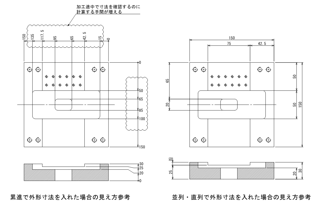
Hole position dimensions
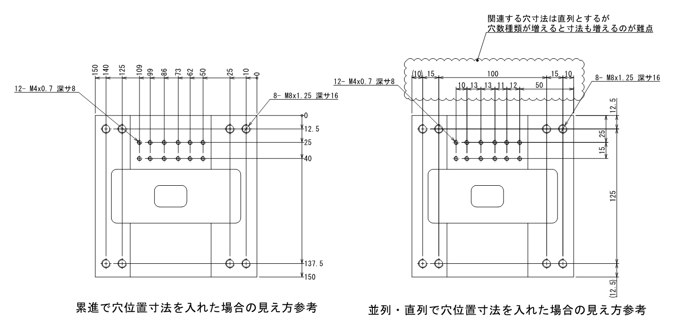
I would like to use these well to represent the drawing.
It would be appreciated if easy-to-measure dimensions are indicated on the drawings.
I was taught by a maître d' and this is the one that fell into the Prefecture. Easy-to-measure dimensions are appreciated.The words.
When we design drawings, we include dimensions that function as part of the machine, but sometimes these dimensions are from the stepped portion on the back side to the stepped portion on the front side of the part as a stand-alone component.But,It's hard to measure from there when making that part.of the product. Especially if the tolerances are tight.
In other words, while putting in the dimensions of what it should be as part of the machine,Sometimes it is necessary to have alternate dimensions, etc. at the stage of makingI think that would be a good idea,Especially with regard to one-shot items.Mass-produced products may be okay because they go through the process of mass production.Of course, it is acceptable to measure only from the stepped portion on the reverse side, but in that case, the work of removing it once during processing and measuring the dimensions would be required,We need to put in the dimensions so that we remember that machining is not about aiming for that value in one shot, but about measuring and reducing to high precision during the process.
That's why parts diagrams are so difficult.
Taps are long and less than 2d.
For tap length,Basically, screw engagement requires no more than 2D(If more than 2D is required, increase the screw size, etc.), so if the design was appropriate, it would not be more than 2D.simplySuch machining is wasteful, and we don't have such tools.That's what I mean. (Beginners especially note,(e.g., M5 penetration in a 50-ton plate)
However, in some cases, we may penetrate more than 2D or 2.5D, so this is a case where design priority is given when we receive a request.
Depth of pockets, etc. is basically "blade diameter x 3D or less".
I'll just note what the person told me.For end mills, the depth of machining is limited to 3D of the tool's diameter.It was.
Then I did a little research on end mills,For a typical end mill tool diameter, there was a lineup of 1.5D, 2D, 3D, and 4D blade lengths.Based on this information, the relationship between the depth of pockets, walls, etc. and the R of the section can also be understood a little.
In other words, if the maximum depth is "tool diameter x 3D", the minimum R at the corner is "(depth h/3)/2 = radius R".and assuming, for example, a depth of 15 mm(15mm/3)/2=2.5R...Pocket with a depth of 15 is a φ5 tool = 2.5R The smallest diameter that can be machined with a minimum of margin (except for special cases, of course) is the smallest diameter that can be machined with a minimum of margin. (except for special cases, of course).
OSG also provides the following information on end mill machining.
Citation: I will quote only the main points.
End mill blade length isThe shorter the length, the more rigid and the better the cutting performance. However, the rigidity of an end mill is inversely proportional to the cube of the blade length (protrusion length), and when the blade length (protrusion length) is doubled, the tool rigidity is reduced to 1/8. End mills areThis is very important because it is a tool that feeds horizontally, and using an end mill with a longer than necessary cutting edge length is a major disadvantage. will be
Source:: OSG Catalog
In other words,I just made a note that it is safe to say that the depth of the pocket or wall should be "less than 3D of the tool diameter".The deeper the endmill, the tougher the machining side is. Therefore, it may be a good idea to have a tool of about max3D for the depth while watching the balance with the surroundings.Depending on the situation, they can process in 4D or even higher, but it may be a good idea to consult with a place that can process there.
End mills are OK with basic pin angles.
The next section discusses the corner shapes of the bottom and walls,There is no in-depth explanation here.
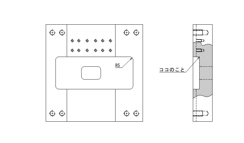
For example, when I stated 0.4R or less, what I thought would be conveyed was the thought that a pin angle of R0.4 or less would be fine, but I meant that it could also be taken to mean that I do not want a pin angle with an R of R0.4 or less.
That is, unless there is a special request.Corner angles should be written in pin angle, and the design should allow for a comma R (0.2 to 0.4) on the end mill blade angleI think we can say that this is the case.
It is easier to measure from the point where the workpiece is cut than from the point where the material is applied to the workpiece.
This is when processingIt is easier to make dimensions from where the material is slightly shaved than from where the material is applied. This means.
What does that mean?
We, designers, think that the distance from the end face is easy to protect and easy to show, but if we imagine the actual machining situation, it would be as follows.
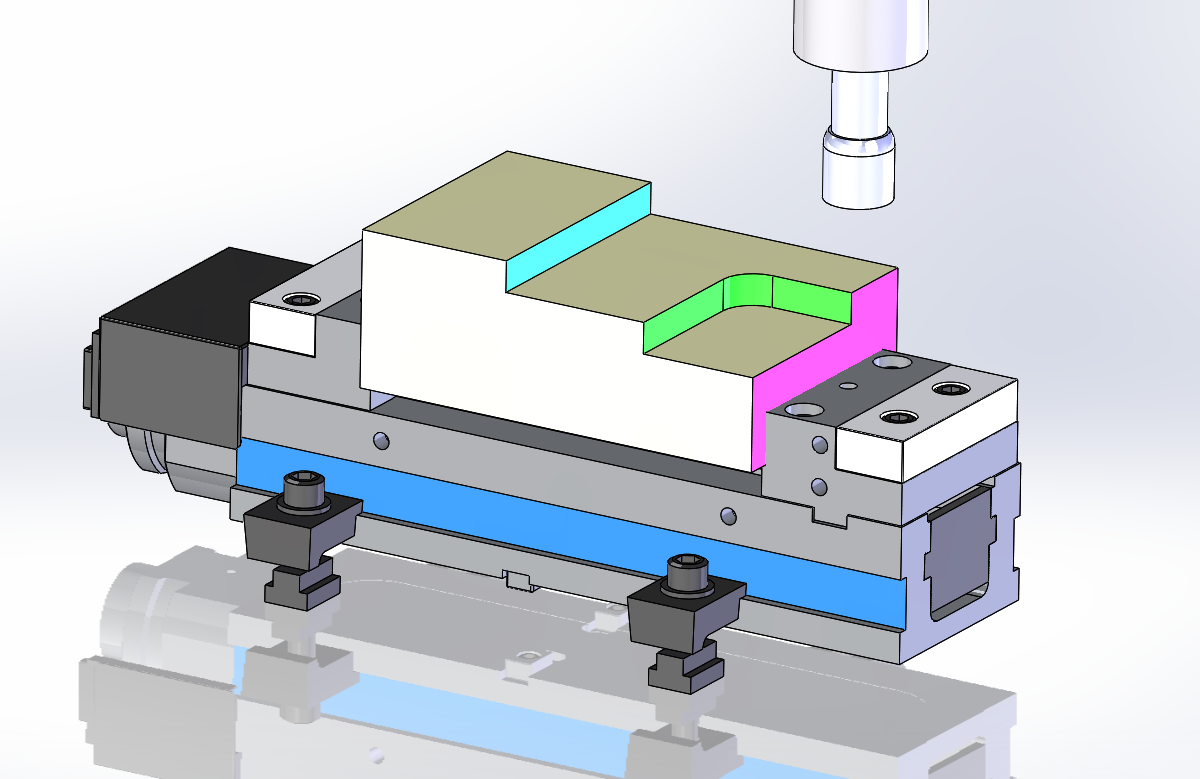
If the purple surface is used as the reference plane without shaving the mounting surface, if the positional relationship of the tool center is "zero error" with respect to the machine's command value, if the diameter of the tool used is "zero error," and if the machine's travel is "zero error," the green position from the reference plane will be obtained, but in reality, various factors will cause error in the relationship. In practice, however, various factors can cause errors, so dimensions cannot be obtained immediately,
It is easier to dimension a light blue surface that is "00 in the X direction" from a green surface that has been shaved than a green surface that is aimed at without shaving.Yes.
However, this is just to say that it is easy to produce, and if the shape is measurable, as mentioned earlier, it is possible to measure once and drive it in, so it is important to make it a measurable shape here as well.
Finally.
I was glad to have a chance to talk with a machining meister for a while this time. He told me that it is important to have a good conversation with the person who processes the part so that both parties can make a good product.
What I wrote today is not the entirety of what the parts should be, but a small slice of what they should be.I think it is, and I would like to continue learning about it.※By the way, we were not able to hear the reasons in depth, so if you can add to this information or point out any errors, we would appreciate it.
That's it.
-

-
Introduction to Mechanical Drawing
Here, I would like to leave a note as an introduction to mechanical drawing, "Thorough Explanation from Basic Rules to Drawing Methods". In mechanical drafting, I have been wondering if I can really convey the ...
See more.
