Here."How to Calculate Deflection of Steel and Excel (Free Software)" This is a note about the This article shares a sheet that calculates how much the steel will deflect when a load is applied to the method of support.
Also, in mechanical designWhen to calculate steel deflectionWhat kind of decision should we make?If you are a beginner in conceptual design, please read this article. I hope it will be of help to you.
Steel Deflection Calculation
When to Calculate Steel Deflection
Depending on the category of mechanical design, production equipment and the like can be relatively large, so deflection calculations are performed for the gantry-shaped frames that support them and for the base frames that serve as the foundation of the equipment.
The reason for the deflection calculation is simple,Wobbly machines are prone to fatigue buildup, breakage, or rupture due to increased load on welds.This can also happen. Often, the deflection of the steel is not calculated and the resulting machine frame is too weak and deflects too much when loaded...To prevent this from happening, steel that has seen safety is used for the machine.
In actual machine design, these deflection calculations are needed everywhere, and many of them require the use of very complex calculations. Nowadays, 3D CAD models can be used to calculate deflections more accurately than traditional manual calculations.However,There are several problems with deflection calculations in 3D design, the first being that you can't calculate deflection without a model.That is to say.
This may sound obvious, but it causes a huge loss of time. When the model is completed, it is relatively late in the process. Therefore, if the model is not strong enough at this point, it is a big loss.Therefore,Steel deflection calculations when designing a machine should be "considered" as early as possible.Flow.
- Selecting the steel material to be used by calculating the deflection of the strength members in the initial stage.
- Check again when the approximate load is visible in the middle of the design process.
- At the end of the design phase, a 3D model is used to analyze the structure in detail to confirm that there are no problems.
I think this is the way to go.
What to think about when looking at the results of deflection calculations.
In mechanical design, especially when you go from being a beginner to being entrusted with design, you are faced with problems that you did not care about before.
What can I do with the steel here?"
Until now, we have selected steel materials based on their past performance without any worries, but when it comes to new equipment, we realize that past performance is only a reference and that we do not even know the basis of how the steel materials we have been using have been used in the first place.
For me, this is the beginning of the design process. Once you get past this problem and learn to calculate deflections and what to do with the results, I think you will find that although the deflection calculations can be tedious, having those calculations done early on will reduce rework in the second half of the project, and you will find great benefit in being able to calculate the deflections.
The main question,What is important in steel deflection calculationsは
- To leave measurable results.
- Understand that it is only a calculation.
- The results of the deflection calculations should also be used to develop a countermeasure plan.
Yes. For example, let's say you pass a square pipe and hang an object in the center of it. To calculate its deflection, we need the following information
- Its structure (cantilevered or fixed at both ends?) Fixed at both ends? etc.)
- Distance to be evaluated
- Longitudinal modulus of elasticity of the steel used
- Cross-sectional secondary moment indicated by the shape in the direction of load application
- load applied
It is. The calculation formula is described at the end of the article and also on an Excel sheet, so please check there. Assuming that the deflection calculation is based on the above information, the answer that comes out is
- Deflection = 0.5mm
The answer is something like. It is difficult for designers to evaluate how to evaluate this "0.5mm". In some cases, 0.5mm deflection is acceptable. If this 0.5mm deflection is NG, how to deal with it?
- Increase the thickness of the plate
- Increase the size of steel
This decision should be made early in the design process.On the calculation, I said, "Yay! I changed the thickness and now the 0.5mm deflection is down to 0.1mm!" is a subtle evaluation.The reason for the subtlety is that the board thickness cannot be made that thick forever, and the question arises whether the structure is good in the first place. And, the question arises as to whether the structure is good in the first place. Also, if you are preoccupied with the small amount of 0.5mm deflection, you will not be able to create a good design.
If I first conceptualize a rough structure and the calculation results show that a deflection of 0.5 mm will occur in this way, I save addressing it with plate thickness for the last minute. The first thing to think about then is what are the disadvantages and what are the advantages of the higher level steel to increase its strength, and how much change in deflection will occur if the shape is changed? This is the first thing to think about. The design of a machine may be superfluous from the initial planning, or the next construction project may need to support a large, heavy object.
In short, it is better to design for later application. Design as much as possible "to make it easy later".We calculate various steel materials, especially when designing in a narrow space, and apply the best steel material that satisfies the deflection in a space-saving shape to it.
Deflection under its own weight that beginners do not notice
In CAD design, steel is drawn straight. I have the impression that it is somehow unbendable,Steel deflects under its own weight。
This is the part you don't notice if you only look at CAD, and it may be hard to visualize, especially for beginners. No matter how hard a bar or how strong a steel material is, the longer it is, the more it will flex under its own weight. You have to imagine it.
Simple Deflection Formula
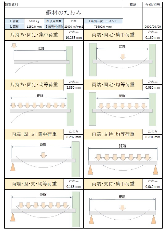
The information required for deflection calculations is as follows
- F Load (kg)
- L Distance (mm)
- E Modulus of longitudinal elasticity (kg/mm2)The modulus of longitudinal elasticity, also called Young's modulus (rate), is a value that expresses the firmness of a material.
- I Secondary moment of cross section (mm4)*Sectional secondary moment is a value that expresses the solidity of an object due to its shape.
- N No. of bottles used (pcs.)
List of deflection formulas for Excel
| Support and load conditions | Formulas for Excel (for copying) |
| Cantilevered fixed, concentrated load | =(F*L^3)/(3*N*E*I) |
| Cantilevered fixation, Equal load | =(F*L^3)/(8*N*E*I) |
| Fixed at both ends, concentrated load | =(F*L^3)/(192*N*E*I) |
| Both ends fixed, equal load | =(F*L^3)/(384*N*E*I) |
| One side fixed, one side supported, concentrated load | =(7*F*L^3)/(768*N*E*I) |
| One side fixed, one side supported, equal load | =(F*L^3)/(185*N*E*I) |
| Both end support/concentrated load | =(F*L^3)/(48*N*E*I) |
| Both ends supported, equal load | =(5*F*L^3)/(384*N*E*I) |
Download Steel Deflection Calculation Excel (free software)
In order to make a preliminary evaluation as quickly as possible, we have re-created an Excel sheet for deflection calculations, which we have uploaded here.
Please try to calculate and include the cross-sectional secondary moment in the geometry of the steel used in the CAD. the second and subsequent sheets have data in the reference material. The current list is as follows. (We will add other steels in the future.)
- Secondary moment of section of square pipe
- MISUMI aluminum frames (HFS, HFSL, NFS, NFSL)
- H steel
- Groove steel (channel)
- I-beam
Please take advantage of this service.
*There are other sites that provide more detailed deflection calculations, so please look for them.
That's it.
-

-
Basic calculations
This section contains notes on the basic calculations for mechanical design that I use in my practice. The articles with calculations and the calculations are revised as needed, so please use the latest version when using them. If you have any questions, please feel free to contact me.
See more.