Here ismechanical drawinginDifference, inclusion, and use of progressive, series, and parallel dimensionsHere is a note about "TheThe method of adding dimensions varies depending on the company and the parts handled.
- Those who want to learn about the differences in dimensions and common notation rules
- For those wondering how to use each dimension differently
- Beginners in design and drafting
This article explains the different types of dimensions and how to use them.
I first wrote this article in 2019, and I am now adding to it in 2023 (present day). In the past few years, the term "drawing-less" has become popular, and services that allow parts to be ordered directly from 3D models have actually emerged. However, the trend towards drawing-less production has slowed down, and some engineers believe that drawings cannot be completely eliminated. I alsoThe drawing cannot be lost, and this skill will be the differentiating factor for designers in the future.is one of those who think so.
Here goes.
Types of dimensions (serial, parallel, progressive) and their characteristics
There are generally three ways to input dimensions for mechanical parts. (Reference: JIS Z 8317-1: Technical drawings — Dimensioning and tolerancing — Part 1: General principles)
- Straight dimension
- Parallel dimensions
- Progressive dimensions
These are all the dimensions.Add dimensions from the part datum.However, there are differences in the rules listed.
Linear Dimensioning and How to Use It
An in-line dimension is literally a method of placing dimensions on the same straight line.It is.
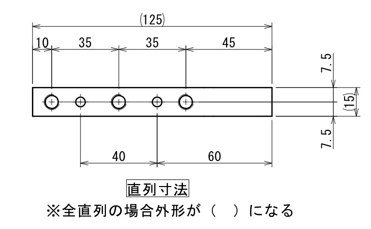
As for the features,Cumulative dimensional tolerancesIt is.
Key points of the in-line dimensioning method
Holes and holes, from the indicated locationsUsed when requesting relative position within a tolerance rangeI will do so.
Parallel dimensionsRecord-keeping and how to use it
Parallel dimensions are a method of creating reference points or datums on a part to which dimensions are applied, and then listing each dimension in parallel from those references.It is.
Characteristics.Each individual independent dimension is subject to its own dimensional tolerance.The following is a summary of the results of the project.
Parallel dimensioning key points
Used when requiring absolute position from the datum plane within the tolerance range.I will do so.
Progressive dimensionsRecord-keeping and how to use it
Progressive dimensions are a method of listing parallel dimensions on the same straight line.It is.
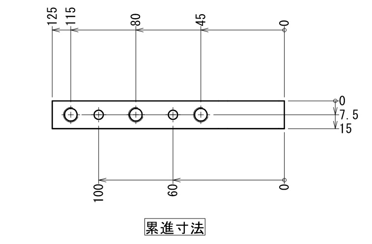
As a characteristic, like parallel dimensionsApply respective dimensional tolerances to individual independent dimensionswhileSpace-saving dimensionsis possible.
Key points of progressive dimensioning
Used when requiring absolute position from the datum plane within the tolerance range.I will do so.
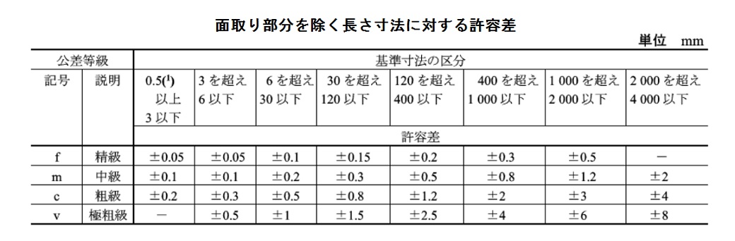
Supplement: Regarding tolerance as used here
Tolerances are not specified here.General ToleranceThis shows both general tolerances and input tolerances. (General tolerances are JIS B 0405)
As seen above, the longer the distance, the moreThe hole's position can be significantly off from the intended location depending on how the dimensions are entered.I believe you can understand.
How to use each dimension (reference examples)
Okay, here's the place that a lot of people are concerned about,How do you use them differently?I will briefly touch upon it.
From my experience reviewing drawings from multiple companies,
- Drawings for can manufacturing and sheet metal parts often mix dimensions that are in series with dimensions that are in parallel.
- Drawings with a mix of serial dimensions + parallel dimensions and drawings with a mix of progressive dimensions + parallel dimensions are about half and half for machined parts.
It is.
I believe that progressive die is not suitable for drawings that deal with can products and sheet metal, so a combination of "series + parallel" seems reasonable.
And next, we have some machine-cut parts that are a bit more difficult.
For simple shapes, there's absolutely no problem with "series + parallel," butFor complex parts, I often use progressive dimensions because they make the part shape easier to see with minimal dimensioning space.However,Progressive dimensions have their own dimensional tolerances applied to each dimension from the datum.So,Tolerances for things like hole spacing require separate series or parallel dimensions.
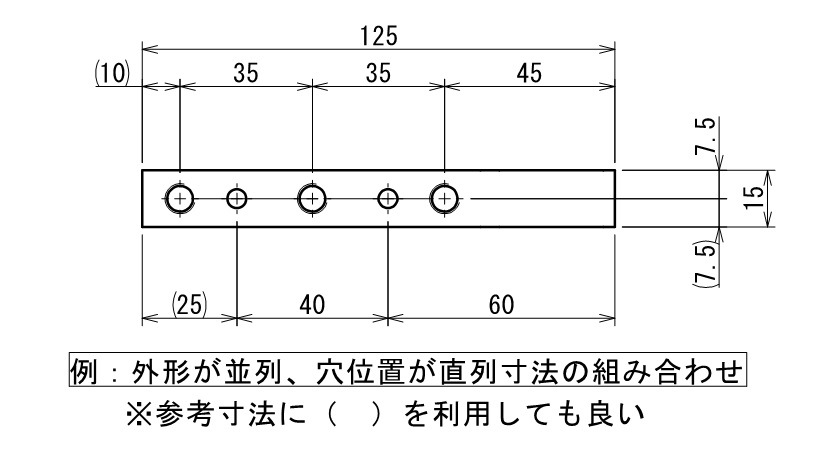
For example, when applying hole-to-hole tolerances to a location dimensioned with progressive dimensions, it would be as follows:
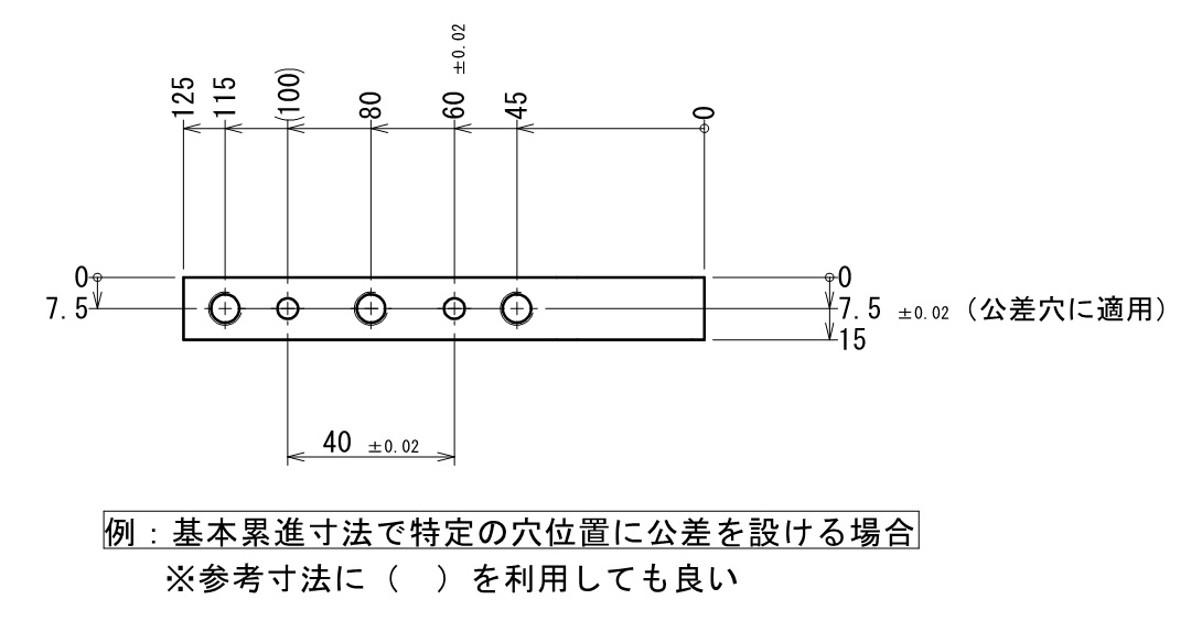
This is how to fill it out.
Progressive dimensions are very convenient, but it can become difficult to read if you put external dimensions and hole positions in the same line. Therefore, if you choose to use progressive dimensions, it is a good idea to separate them by attributes such as holes and surfaces. (This method is often seen in precision equipment parts.)
Personally, I think...
Personally, I also use progressive dies, but basically, I don't differentiate how dimensions are applied for can parts and machined parts.
- When the external dimensions and hole dimensions are closely related, they are called serial dimensions.
- For external and hole dimensions, change the step for unrelated locations with parallel dimensions.
This shape might be the easiest to understand. (It's a matter of the drafter's sense, I think.)
Finally.
This time, I wrote an article about the basic usage of dimensions, but inputting dimensions is surprisingly difficult.It is also important to place dimensions in a way that does not interfere with the shape being represented. Furthermore, it is important to place dimensions in the most easily understandable location from the perspective of the manufacturer or inspector viewing the drawing.
That's it.
-

-
Introduction to Mechanical Drawing
Here, I would like to leave a note as an introduction to mechanical drawing, "Thorough Explanation from Basic Rules to Drawing Methods". In mechanical drafting, I have been wondering if I can really convey the ...
See more.
