Today, for those who are new to compression spring design, "TheBasic design and selection guidelines for compression springsHere is a note about "The
Commercially available compression springs come in a wide range of sizes and specifications In many cases, we FA machine designers purchase relatively small compression springs that meet the specifications of our machines.
And there are many variations of compression springs.In design and selection, it is difficult to know where to start, and it takes time, especially for those who are new to selection. I, too, do not design, select, and purchase frequently, so it takes me a long time to select the next time I buy.Most of the calculations for compression springs in books and websites basically involve putting in some numerical values as a trial and then fine-tuning them by evaluating the results of the calculations (e.g., whether they are within the allowable range). There are a lot of technical terms, and I think designing compression springs is a hurdle for beginners.
So, today we are going toShare a calculation sheet that allows you to find the approximate spring dimensions by simply entering the specifications you want, and then make your selection based on that guideline. I will try to provide an easy-to-understand explanation even for beginners while doing so.Please check it out.
Compression spring design and selection method
Now, we will note down the knowledge required to calculate and select the compression springs, so please download the document (Excel calculation sheet) and review it with us if you need it.
The calculation sheet is simple and does not include details such as dynamic or static use, so it is easy to grasp even for those who are designing springs for the first time.
What you need to know about compression spring design and why
Compression springs areThe high degree of design freedom makes it easy to design many differently flavored designs. I am not sure what to expect,There are indicators that the finished spring should be in the following conditions So, I will note those items and the reasons for them.
(1) Ideal aspect ratio should be within 0.8 to 4
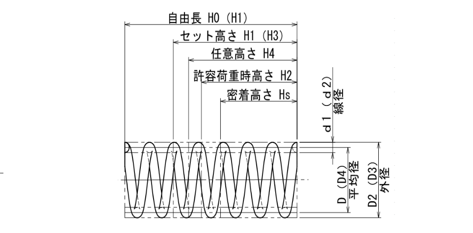
The aspect ratio is calculated by "aspect ratio = free length / center diameter.
It is recommended that the aspect ratio of the finished compression spring be between 0.8 and 4.0 or less. The reason is that the number of effective coils cannot be secured for a ratio of 0.8 or less and the variation of spring characteristics will increase, while a ratio of 4.0 or more requires a separate guide that takes into account the buckling of the spring. (If a guide is used, it may be exceeded.)
(2) Pitch of spring circumference is 0.5D or less
If the pitch exceeds 0.5D (0.5 x average diameter D), the average coil diameter will change as the load increases, so a pitch of 0.5D or less is recommended.
(iii) The use area R of the spring should be within 20 to 80%.
The MAX and MIN range of motion for compression springs are the unshrunk free length (MAX) and the fully shrunk close contact length (MIN).The spring's working area, which is the actual working position between the free length and the contact length (total deflection), should be within 20 to 80% of the total deflection.
(4) Spring index should be in the range of 4 to 22.
The spring index is a numerical expression of the relationship between the average spring diameter and the wire diameter. It is recommended that the spring index be designed within the range of 4 to 22.A spring with a low spring index is a stiff spring with elasticity due to its relatively thick wire diameter, while a spring with a high spring index is a soft and fluffy spring with a relatively thin wire diameter.
The trends related to the design of different spring indexes are as follows
- Spring index too low: spring constant tends to be high, easy to break
- Spring index too high: spring constant tends to be low, easily deformed
Actually designing a compression spring
Calculations based on the above guidelines,With the two pieces of information, the actual set height you want to use and the force you want to press against it at that time, you will have an approximate idea of the shape of the compression spring.
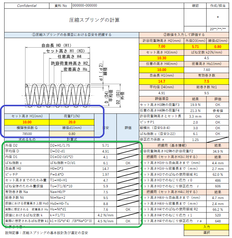
*When you enter the information in the blue box area on the left side of the calculation form, you will see the tentatively calculated spring dimensions in the green box below. And,The calculations we will be sharing with you are based on the approximate calculations so that the inside of the green box will be as follows
(1) Approximate calculation formula for compression springs
The following is included in the Excel spreadsheetCalculation formula to determine the base shape of a compression spring (rough guide) based on the set height H1 (mm) and load F1 (N) It is.
(1)-1 Outer diameter D2: D2=H1/1.75
*Outer diameter is calculated 1.75 times the set height.
Average diameter D: D=D2-d1
①-3 I.D. D1: D1=D2-(d1*2)
(1)-4 Spring index c: c=D/d1
①-5 Free length H0: H0=D*3
※Calculated with aspect ratio of "3
①-6 Pitch P: P=0.4*D
Calculated as average diameter x 0.4
①-7 Deflection to set height: T1=H0-H1
(1)-8 Tentative value of overall spring deflection: Ts=(T1/8)*10
(1) - 9 Number of effective coils Na: Na=H0/P
①-10 Total number of windings Nt: Nt=Na+2
Hs0: Hs0=H0-Ts
(1)-12 Actual assumed adhesion height Hs: Hs=Nt*d1
(1)-13 Spring constants at tentative values k: k=F1/T1
(1)-14 Assumed actual spring constant k1: k1=(G*d^4)/(8*Na*D^3)
The fixed and selected values are as follows
- Fixed at transverse modulus of elasticity G: 78500 N/mm2
- Wire diameter d: Selected from commercially available spring wire diameters
In this grasping calculation, a difference is made between the tentatively calculated spring constant and the actually assumed spring constant, since the calculation is performed with partially tentative values.Therefore, at the end of theActual production is possible by selecting and adjusting wire diameters, and calculating compression spring dimensions to the targeted specifications. Specifically.Adjust the spring constants so that the hypothetical spring constants and the actual assumed spring constants are closest to each other. The statement determines the difference here as +/- 20%. (20% is my setting)
In addition, some of the initial two input items may generate NG results when calculated with extreme values.Of course, the above settings are treated as standard settings, and you will be able to use this spreadsheet as you go along.You will probably have your own preferences, so please arrange and use them.(e.g., I like a higher spring constant → I'll lower the aspect ratio from 3 to 2.75, etc.)
The modulus of elasticity is The modulus of elasticity fixed in this statement isLateral modulus of elasticity of SWPA and SWPB in spring spring constant calculations If you need a more detailed explanation, please refer to the following page.
Select and evaluate commercially available springs
Now that the reference dimensions are known, the next step is to select a compression spring that is close to the reference dimensions from among those available on the market, or to manufacture a new one.
Note the case for selection ahead of time.Here we note a representative of the selection process at MISUMI, which is often used by everyone.
- Determine the material *Select the material entered in the calculation sheet. ⇒I think SWPB is fine unless otherwise specified.
- Select allowable load (range specification)(N) and refine.
- Select all the values for which the allowable (maximum) load (N) on the misshapen side is greater than the value of the reference calculation.
- Narrow down the list by selecting all cases where the allowable load height H2 (mm) is close to the set height H1 and lower than the reference calculation (-2 mm lower).
- Select the coil outer diameter OD(φ) closest (±1mm) to OD(φ) D2 or the closest one or one before and after each other to narrow down the selection.
- Select the spring constant k(N/mm) that is closest to the spring constant k(N/mm) and narrow down
- If the selection is not narrowed down to one model at this point, the one with the closest wire diameter d(φ) is selected and confirmed.
Finally, the selected springs are input into the calculation sheet to determine if they can be used in practice, including stresses. (For the stresses, a graph showing the tolerances is attached on the second sheet.)
If this selection is far from the guideline, the spring should be newly manufactured or the design should be adjusted so that the commercially available product can be used.
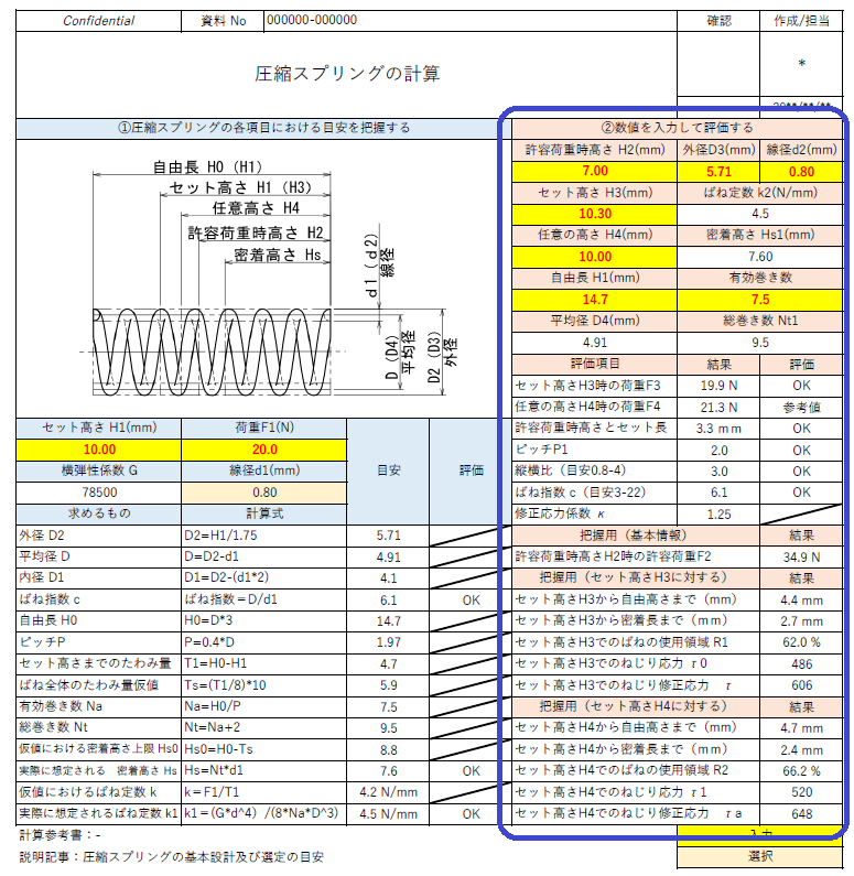
(2) Compression spring confirmation formula
Below is the confirmation formula for the selected and designed springs. This formula is the formula used in each web site and selection software. (Calculation Excel uses two positions, but the formula is shown here for one position only.)
②-1 Average diameter D4: D4 = Outer diameter D3-Wire diameter d2
2-2 Spring constant k2: k2=(Lateral modulus of elasticity G*Wire diameter d2^4)/(8*Number of effective windings*Average diameter D4^3)
②-3 Total number of windings Nt1: Number of effective windings+2
②-4 Adhesion height Hs1: Hs1 = Total number of coils Nt1*Wire diameter d2
②-5 Load F3 at set height H3: F3(N)=(Free length H1-Set height H3)*Spring constant k2
②-6 Pitch P1: P1=Free length H1/Number of effective windings
②-7 Aspect Ratio: Aspect Ratio= Free length H1/(Outer diameter D3-Wire diameter d2)
②-8 Spring index c: c= Average diameter D4/Wire diameter d2
②-9 Modified stress factor κ: κ=(4*Spring index c-1)/(4*Spring index c-4)+0.615/spring index c
②-10 Set height H3 to free height:Free length H1-Set height H3
②-11 set height H3 to close length:Set height H3-Close contact height Hs1
R1 is the area used by the spring at the set height H3:=(Free length H1-Set height H3)/(Free length H1-Close contact height Hs1)*100
②-13 Torsional stress at set height H3 τ0: τ0=8*Average diameter D4*Set loadF3/(PI()*Wire diameter d2^3)
②-14 Torsional modified stress at set height H3 τ: Torsional stress τ0*Modified stress factor κ
New springs to be fabricated.
If the commercially available springs selected based on the above calculations can be used, it is OK, but if not, new springs must be made to match the design.
newWhen designing springs in the same way as for purchased products, though, we will input the same information as for purchased products,Basically, you can use the same dimensions and number of rolls you are considering on the left.It is. As for spring fabrication, it is my experience that spring makersThe response is very polite, fast, and gives me advice on the specifications I want. Rather than forcing the use of commercial products, consult with us when production numbers are expected or when you really need a one-of-a-kind product.
Finally.
This simplified calculation for compression springs does not take into account the use of repetitive loads (dynamic loads),When using dynamic load, please be sure to check with the spring manufacturer to confirm that the selected spring is available.
Finally, I will post the calculation sheet again.
That's it.
RELATED:Spring