Today, we are going to discuss the "How to determine the length of cable bearers, number of links, and the dimensions of a clean installation, and the size of the openingHere is a note about "TheThere are two basic things that the mechanical design side should pay attention to when selecting and installing cable bearers.
- Do not increase the density of cables and hoses in the cable bear
- Proper installation.
These two are the basic ideas, but for proper installation of [2],See margin for strokes that move. And,Slightly higher mounting height This is called a "cable bear". While this is common, it takes a little time to understand if you are new to cable bearers.
How do I determine the dimensions (number of links) of the cable bearers?andHow should it be written on CAD? Today, theThe following are some additional notes on the calculation method and dimensioning.
Please note that this article is a calculation for general cable bear installation for all types of applications and does not include the following special use calculations.
- Installation with support rollers
- Installation with support plate
- Long span specification
- Calculation of cable bear dimensions
- (1) There must be a margin allowance for the installation height of cable bearers.
- (2) The length allowance is sufficient for one to two links on the fixed and operating sides.
- (iii) To understand the mechanical full stroke and the actual stroke used.
- (iv) Caution! There are cable bearers that are not either fixed fixtures or stroke-centered.
- Calculation Excel sheet
- Supplement 1: Concept of selecting aperture size for cable bearers
- Supplement 2: Design method for radius R of cable bearers (cable carriers)
Calculation of cable bear dimensions
When a cable bear is represented in a drawing, some people may say that the shape of the cable bear before and after it moves is somewhat unsymmetrical. (It is not exactly symmetrical.)
This is due to a lack of proper calculations, though,We want to install cable bearers without waste in the design.It is.
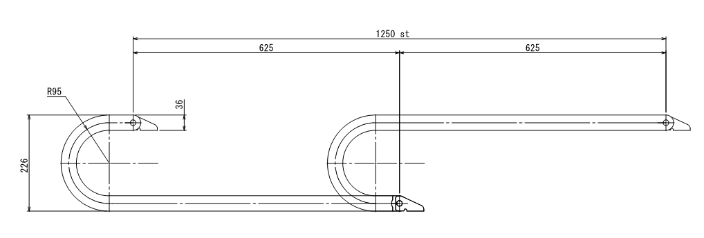
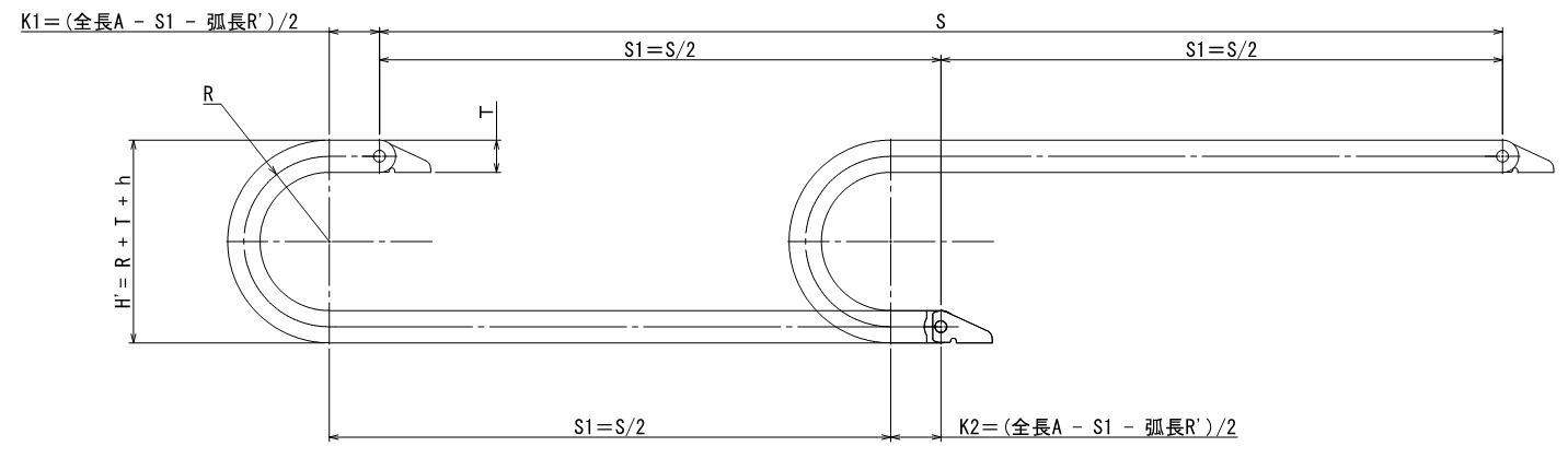
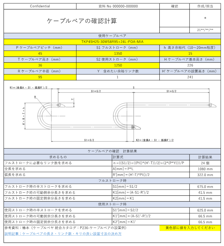
To install cable bearers without waste, as shown in this figure,Cable bear shape before and after movement must be calculated carefully.Is. Above.The reference data in the table below is a combination of two downloaded CAD data of Tsubakimoto Chain's TKP45H25 for the 1250st before and after operation.
However,Actually, it can't be used as is for CAD data.They are. Here is a description of them.
(1) There must be a margin allowance for the installation height of cable bearers.
First,Cable bear installation height dimensions require a margin of allowanceIt is.
A margin for installation is required at dimension "226" in the figure above. The reason,The cable bearers themselves are slightly bulged at the top to compensate for the weight of the main unit and the deflection of the cables and other components. Therefore, if the cable bearers are installed at the height of "226" above, they will be suppressed, which may shorten the life of the cable bearers (this is true for any manufacturer's cable bearers). (This is true for cable bearers from any manufacturer, and is noted in their catalogs.)
The,Minimum margin is often between 10 and 20 mm.The margin here also varies from model to model, so it must be greater than the minimum installation height specified. Since the margin here also varies with each model, it must be greater than or equal to the minimum installation height specified. The dimensions of each type are as follows.
By any installation height,The total length of the cable bear (number of links) must also be determined. However, please be assured that a difference of 10 to 20 mm will not significantly affect the number of links.
(2) The length allowance is sufficient for one to two links on the fixed and operating sides.
Next to the installation height, the next thing to pay attention to is the length margin. In this case, the length allowance of 45mm is acceptable because the links are 45mm in pitch.(I think in many cases, the catalogs say that the pitch dimension is greater than or equal to the pitch dimension of each model.)
Of course, this example is a 1250st drive, but if the mechanism requires a margin of 50st each front and rear, a cable bear capable of a full stroke of 1350st should be selected, in which case,Arrange for a stroke that can move about 1-2 link percent longer than the maximum mechanical stroke used. It is necessary to
(iii) To understand the mechanical full stroke and the actual stroke used.
For example, suppose the stroke used is 1250st and the design is 1300st up to the mechanical stopper. In this case, it is necessary to draw a cable bear that can use 1350st at 1250st. If the model (diagram) here is neglected, interference may occur in the actual machine, so be sure to make appropriate calculations and reflect them in the drawing.
The following calculation sheet is designed to calculate and understand them as well.
(iv) Caution! There are cable bearers that are not either fixed fixtures or stroke-centered.
This calculation sheet is a generalCable bearers with the fixture centered on the stroke, but some do not have the fixture centered on the stroke. So this calculation sheet may not work for some cases. (Igus may have many of these types of)
Therefore, it is preferable to download the data from each manufacturer if possible, but if you need to input and calculate the cable bear dimensions, please refer to the following for your calculations
Calculation Excel sheet
Here you can download a spreadsheet from which you can calculate the above. The yellow area is the input. Please use it.
Supplement 1: Concept of selecting aperture size for cable bearers
The height of the inner dimension of the cable bear isGenerally, the outer diameter of cables and hoses should be selected to fit within 30% of the inner height. It is considered to be a
In addition, the occupied area is generally considered to be "within 30% of the inside height x inside width," but in my case, I installed a hose model, selected a width that I thought would allow enough room, and designed the layout to allow approximately 10% of the maximum diameter for spacing between the inside walls and adjacent cables and hoses. (This is only a guideline)

Supplement 2: Design method for radius R of cable bearers (cable carriers)
For information on how to design the radius R, see the separate article "How to set the radius R of cable bearers (cable carriers)Please refer to the detailed summary in Section 2.1.
That's it.