Today, we are going to discuss the "Basic calculation of motor torque for horizontal conveying with ball screwA note on "The As a component of the machine.
- The LM guide is used as a slide mechanism.
- Driven by motor + ball screw
However, designing with this ball screw is a bit time-consuming. (It does take time, doesn't it?).
Particularly troublesome is the calculation of motor capacity (torque). It is very difficult to make a mistake here, so today we willCalculation of required motor torque for horizontal conveying with LM guide + ball screw Note the following.
Note: This article notes calculations with the motor directly attached (no reduction gear).
- Basic calculation of motor torque for horizontal conveying with ball screw
- Items needed to calculate motor torque
- Required rotation speed of ball screw
- Required motor speed
- Resolution required for servo motor encoders and drivers
- angular velocity
- angular acceleration
- Frictional torque due to external load
- Overall moment of inertia
- Torque required for acceleration
- Servo motor torque required for acceleration
- Servo motor torque required at constant velocity
- Servo motor torque required during deceleration
- Simplified calculation of 1-cycle effective torque (acceleration → constant velocity → deceleration → stop)
- Calculation Excel Reference
- Items needed to calculate motor torque
Basic calculation of motor torque for horizontal conveying with ball screw
Items needed to calculate motor torque
The following items are required to calculate the motor torque required for horizontal conveying with LM guide + ball screw.
- K Conveyance mass [table + workpiece] (kg)
⇒ Please calculate by hand or CAD
- V Conveyor speed (m/s)
⇒ Check design specifications
- E Accessory moment of inertia attached to ball screw (kg-m^2)
⇒ Couplings connecting motor and ball screw, etc.
- J Ball screw moment of inertia (kg-m^2)
⇒ If it is difficult to figure out the detailsThis "cylinder" here Please make a simple calculation with
- D Motor side moment of inertia (kg-m^2)
⇒ Get information from the motor catalog.
- L Ball screw lead (mm)
⇒ Need the lead of the ball screw you are planning to use.
- t Acceleration/deceleration time [s].
- t' Constant velocity time [s].
- St Stop time [s].
⇒ Acceleration and deceleration greatly affect the required torque of the motor.
basicallyShort acceleration time = large motor torque The first two are the following.
If you want to calculate driving speed, time, and distance traveledOperation Pattern Please check with the
- S Minimum feed rate (mm/pulse)
⇒ Check design specifications
- Y Feed pressure torque (N-m)
⇒ To ball screwGiving pressurization interferes with rotation.If you want to give pressurization because ofPressurizing torque Please check the
- H Reduction ratio
⇒ Required when applying deceleration
- C Other load torque (N-m)
⇒ Include any other load torque if any.
- P Guide surface resistance (N)
⇒ Set the assumed value on the design side. If you have the actual product, measurement is also acceptable.
- U Safety Ratio
⇒ Set and adjust by design.
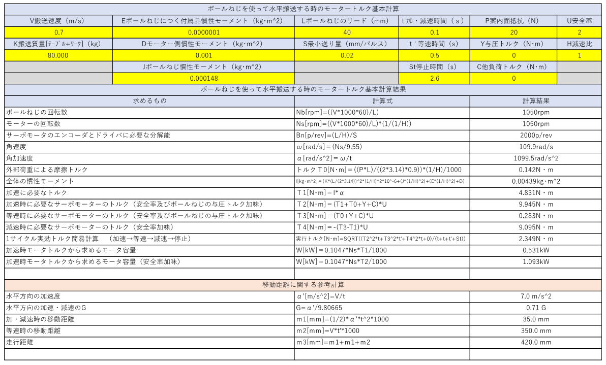
Required rotation speed of ball screw
First, determine the required rpm of the ball screw. If the motor is directly attached to the ball screw, the required number of rotations here replaces the number of rotations of the motor.
Nb[rpm]=((V*1000*60)/L)
Required motor speed
Find the required number of revolutions of the motor. Here, the calculation is based on the case where a reduction gear is engaged. In case of direct mounting of a motor, "the required number of rotations of the ball screw = the required number of rotations of the motor.
Ns[rpm]=((V*1000*60)/L)*(1/(1/H))
Resolution required for servo motor encoders and drivers
If servo motors are used, determine the required resolution for the driver. This is necessary to consider whether the stopping accuracy can achieve the desired point.
Bn[p/rev]=(L/H)/S
angular velocity
Angular velocity is calculated by the following formula.
ω[rad/s]=(Ns/9.55)
angular acceleration
Angular acceleration is calculated by the following formula.
α[rad/s^2]=ω/t
Frictional torque due to external load
Find the frictional torque due to external load.
Torque T0[N-m]=((P*L)/((2*3.14)*0.9))*(1/H)/1000
Overall moment of inertia
The overall moment of inertia can be calculated by the following formula.
I[kg-m^2]=(K*(L/(2*3.14))^2*(1/H)^2*10^-6+(J*(1/H)^2)+(E*(1/H)^2)+D)
Torque required for acceleration
The torque required for acceleration can be calculated by the following formula. (This torque is required purely for acceleration.
T1[N-m]=I*α
Servo motor torque required for acceleration
This is the acceleration torque required for the servo motor. This torque must be exceeded by the instantaneous maximum torque of the servo motor under consideration.
T2[N-m]=(T1+T0+Y+C)*U
Servo motor torque required at constant velocity
The servomotor torque required at constant velocity can be calculated using the following formula.
T3[N-m]=(T0+Y+C)*U
Servo motor torque required during deceleration
The servomotor torque required for deceleration can be calculated using the following formula.
T4[N-m]=-(T3-T1)*U
Simplified calculation of 1-cycle effective torque (acceleration → constant velocity → deceleration → stop)
The running torque can be obtained by the following formula.The rated torque of the servo motor under consideration must exceed this running torque.
Running torque [N-m]=SQRT((T2^2*t+T3^2*t'+T4^2*t+0)/(t+t+t'+St))
Calculation Excel Reference
Creating such calculations can save design time.
About Excel files
Thank you for the many people who have used the above machine tact, timing, and time chart diagram. Starting in 2024, this file will beDownload sales at BASE The following is a list of the products that are available for purchase. If you need it, please use it after purchase.
That's it.