Here.mechanical drawing inHow to draw assembly drawingsNote about "The following is a brief description of the "A" and "B" in the "A" and "C" sections.
With the spread of 3DCAD, there seem to be fewer opportunities to draw assembly drawings than in the past,Assembly drawings are not the only drawings needed for actual assembly. Therefore, it is a good idea for mechanical designers to be able to properly draw this assembly drawing at any time.
How to draw assembly drawings
What is an assembly drawing?
An assembly drawing is a drawing of a finished product that consists of multiple parts, and while it is easy to write a drawing for a product that consists of only a few parts, it is not so easy to write for a product that consists of only a few parts.The more parts there are, the more difficult assembly drawings become.
For those who don't know how to draw assembly drawings (especially beginners), I think it is a pain to make assembly drawings.What is written on the assembly drawings is a mass of know-how that is created only inside each company and is not exposed to the outside world. It is.
Therefore, no designer can draw assembly drawings from the beginning, and it takes many years and various experiences to be able to draw optimal assembly drawings. In my case, since I use 3D CAD, each side can be drawn in an instant, and the cross section can be done freely. I don't have to punch in balloons, and the load is less than when I was using 2D CAD, so it's not so hard.
I rather like this work.
The assembly drawings, whether CAD or hand-drawn, require the same elements,What should an assembly diagram look like? The following is a memo on how to draw an assembly diagram, with the following as the axis.
Assembly Drawing Definition
Does everyone know the definition of an assembly drawing? The Manufacturing Web's "How to Draw Assembly Drawings - Fundamentals for Mechanical Design EngineersThe "Mere Old Man" has this to say about it.
Quote (from Monozukuri Web)
Assembly drawings are presented in three views (front, plan, and side views) to show the entire product, and other projections and cross sections are added as needed.
The assembly drawing should include the outermost dimensions of the entire product (the size of the product).
Elsewhere, going dictionary-related, here's what I found.
Citation (from Osharlin).
A drawing that expresses the state of cohesion in terms of function or handling by assembling multiple parts.It is also called an assy diagram, to distinguish it from a parts diagram.
Although assembly diagrams alone provide an overall picture of the target product or part, they tend to lack the amount of information on the details of individual parts and parts. To supplement this, parts diagrams and detailed drawings are often used in combination.In the case of simple assembly drawings, a technique is also used in which the individual components are also marked with their shape dimensions and specifications to serve as both parts and detail drawings.
The above is a description of the assembly diagram.In short, the way assembly drawings are drawn is up to the designer. You can see that this is the case.
There are three main items required for assembly drawings
Now, here are my thoughts.
In drawing assembly drawings, the base ideas are"Something that everyone can see and understand what's going on." However, there are three major items that need to be included in the assembly drawing for this purpose.
- For designers and facilities managersCapability values (text) Doing.
- For assemblers and adjusters,Information for assembling the machine (dimensions, balloons, etc.) Doing.
- List the parts list and balloons needed to place the order. Doing.
These are the three. When a machine consists of multiple units, assembly drawings are created for each level of the hierarchy, such as overall view, partial assembly view, and so on.
- Overall view (Unit A/B/C combined)
- Unit A Assembly drawing
- Unit B assembly drawing
- Unit C Assembly drawing
Here is the image.
(i) Competence values for designers and facility managers (text and tables)
The first, capacity value (tolerance) for "designers and facility managers" means that this machine isThe ability to describe in numerical values such things as how it moves at what speed, how it relates to other equipment, and the maximum payload capacity. It is.
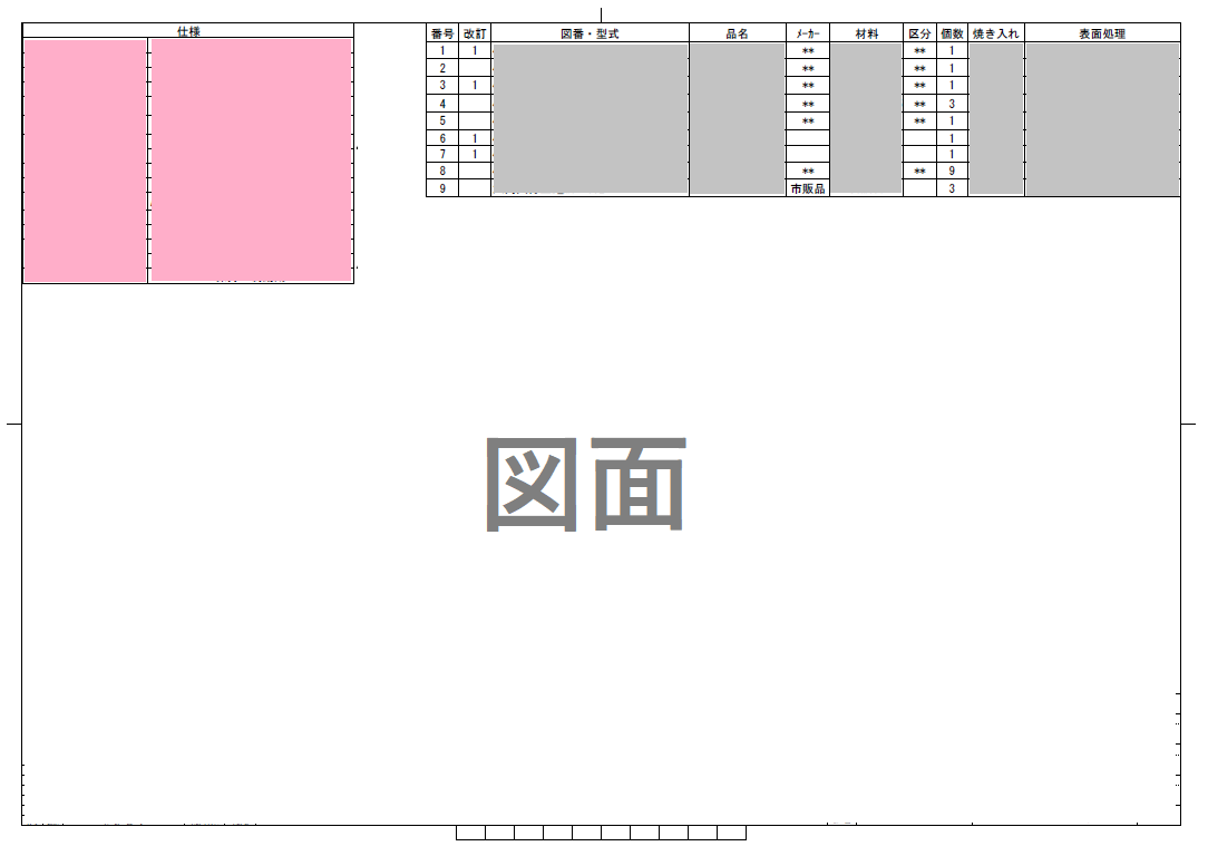
In the above figure, the light red area in the upper left corner is used to create a table of items on the left and values on the right (the upper right corner is a table of parts). (By the way, the upper right is a parts list.)
At the beginning of this article, I mentioned that the drawings are not only necessary for the actual assembly, but this is exactly the part So, assembly drawings drawn here will be used for DR, or go around to departments that do not open CAD models, and assembly drawings will be needed even before the design is completed. The advantages of bringing assembly drawings to DR areThe ability to look at the machine from a bird's eye view, and to see all the dimensions that would otherwise take time to check on the model. It is.
Many people who say that assembly drawings are unnecessary also say that they are unnecessary because now they can assemble the models while looking at the 3D models, but I personally think that is half right and half wrong, since the need for assembly drawings changes for each situation, and they are also used for points other than assembly such as DR.
(ii) Include information (dimensions and balloons) for assemblers and adjusters to assemble the machine.
The second, for "assemblers and adjusters," will include information for assembling the machine. For example,
- I can add comments such as how to apply and fix the parts to each other, etc.
- Certain adjustment screws need to be installed with these dimensions, or make comments such as
- The tightening torque for a particular screw is how many N・m.
- The height of the conveyance level is this height.
Contents include.Some methods can only be expressed in words as above, but basically they are often expressed by "dimensions" It is. How to include assembly drawing dimensions will be discussed later in the article.
Dimensioning and comments on key points areI think it would be good to draw assembly diagrams from the perspective of each person involved, as the person in charge. What kind of information does the person in charge of the project want to read from the assembly drawing? What kind of information does the person in charge of the project want to read from the assembly drawing?
(iii) Place the parts list and raise the balloons linked to it to each part.
The assembly drawing showsThere's no leakage.bill of material and need balloons that do not forget to raise It is.
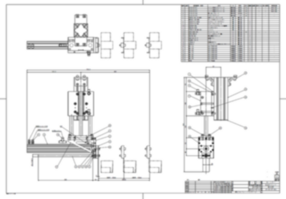
The image is a little messy as it was created for an original image for image understanding......................
Which parts will be attached where, whether washers are required for fastening, whether the material is SUS, and so on,Follow the balloon to detailed information so that you can check it. if you don't mindReference to the table of parts required in the drawing for more information.
Like this,Assembly drawings are drawings that show the external shape, dimensions, specifications, and configuration of the unit in question. refers to
Very Important in Assembly Drawing
What I think is very important in drawing assembly diagrams isAwareness of writing something that anyone can see and understand what is going on. I think that is a good idea.
That drawing will be used by many people in the future. A drawing is an important thing that determines future possibilities.How much future efficiency can be achieved in just one minute of thinking about the layout? If it is so simple and easy to understand that anyone can figure it out, the time spent looking at the drawings of the people involved may be a short time individually, but collectively it can be quite effective.But not if you see it simply as drawing. It is.
Citation:The Role of Drawings and Draftsmen's Awareness
The drawings, both assembly and parts drawings, are not identifiable who will see them. In particular, the way assembly diagrams are drawn is a matter of taste.
I don't know who will see the assembly diagram, but I don't know what level of hierarchy will eventually see it,The only way is to increase your own way of expressing and expressing yourself as you gain more and more experience. I believe that this is a good idea. Even for the layout of the drawings,If you want to show where you need to include dimensions and notes, you will naturally decide on the front, plane, right side, partial detail, and sectional views, etc. I think.
andA clean drawing fits the job nicely. We, as designers, think it is important to be particular about assembly drawings, as they can be used to create a more accurate assembly.
How to include dimensions in assembly drawings
Next,「How to include dimensions and text in assembly drawingsAbout.With the spread of 3D CAD, there are now more and more opportunities to assemble while viewing 3D models.I believe that this has led to a tendency to focus on the "usability of the model," which has led to a decrease in the amount of time and care taken in teaching how to include dimensions in assembly drawings.
However, it is not the case that assembly drawings are unnecessary in the future. This is because as I design various machines, there will inevitably be points where assembly drawings will be necessary. They have an important role not only in assembly, but also in communication between designers in order to make meetings more efficient.
How to insert assembly drawing dimensions and order
In fact, it is best to explain using reference assembly drawings, but drawings are not something that can be made public, so here we will tell you in writing how to include dimensions in assembly drawings.
The dimensions to be included in the assembly drawings can be described as (1) to (6) + supplemental information as follows, but the assembly drawings are not required.Basically, parallel and parallel dimensions are used instead of progressive dimensions. This is because the ideal dimensions are easy to recognize while measuring and assembling on site during actual assembly.
Also, it is important to convey the message, so if the layout is difficult to dimension or grasp, it would be good to correct the layout while dimensioning.
(1) Insert overall and approximate dimensions
On the assembly drawingRequired dimensions, first is the overall and approximate dimensions Is. Mainly.
- over-all length
- overall width
- overall height
- division position
- Other guideline positions
It is. (The image below is for a flat surface)
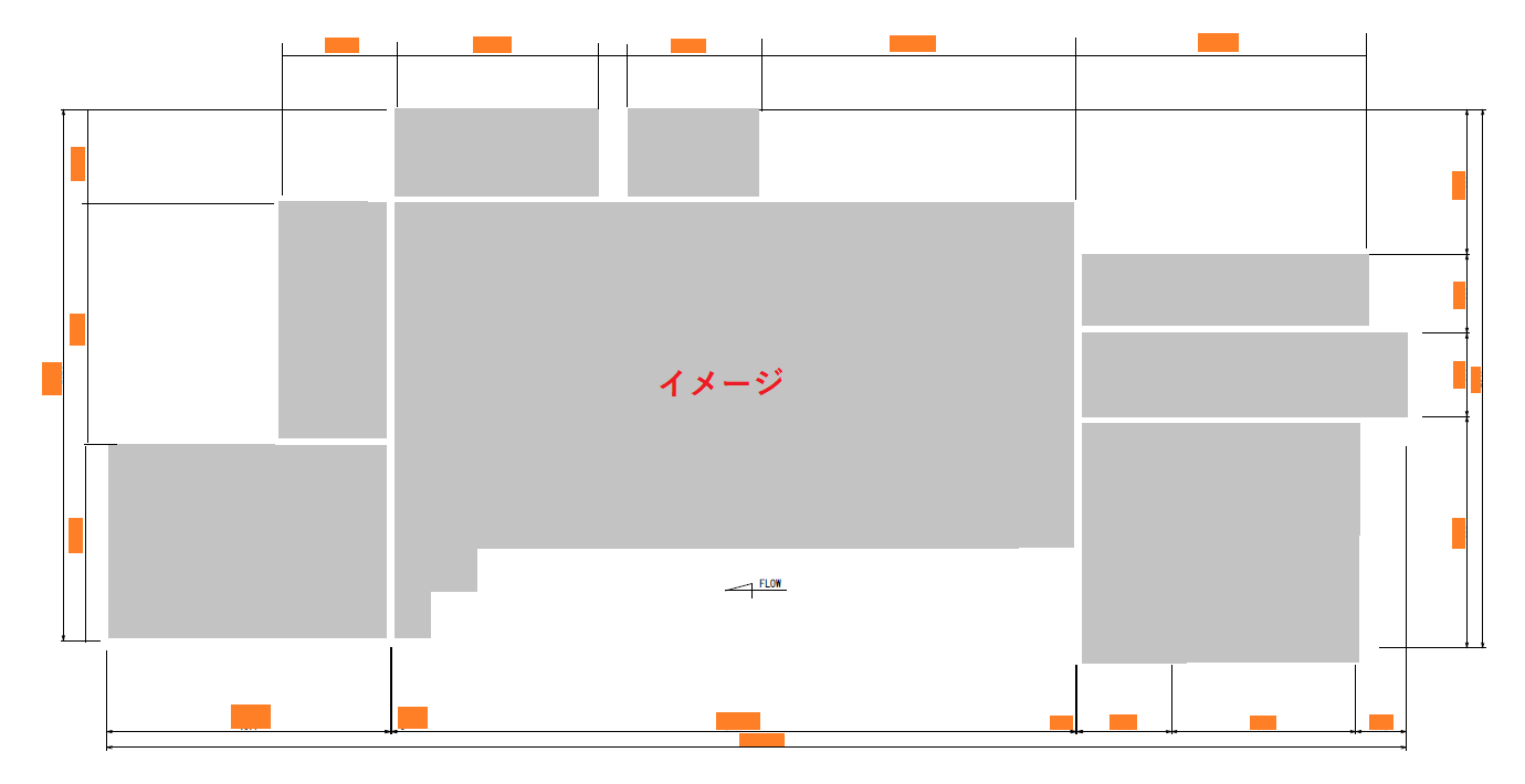
There are two overall dimensions I'm generally aware of The overall dimensions include the cover and the overall dimensions of the device itself without the cover.If the cover is attached to the equipment, the overall dimensions are taken as the dimensions including the cover, but if the cover is separated from the equipment and stands on its own, a distinction is made between the maximum dimensions including the cover and the maximum dimensions of the equipment inside the cover (such as actually making a second drawing), and dimensions are also included for how much space is available.
The purpose of including the overall dimensions is to grasp the overall scale, but even if the maximum dimensions are included, it is necessary to include the subtle protrusion of screws, etc.Fractional dimensions that are difficult to determine are not added unless necessary.
(2) Enter the standard dimensions of the machine.
Next, put in the reference dimensions of the device.There are also two main standard dimensions Yes, there is.
- Reference dimensions where the equipment is installed (e.g., center of equipment, center to end face of equipment, and setting positions of other constituent parts)
- Specification standard dimensions of equipment
The above two.
The first is the reference dimensions where the equipment is installed. The first is the reference dimensions where the equipment is to be installed, such as where in the building the machine is to be installed and how far out to the left or right it is from the center of the equipment.
The second is the specification standard dimensions of the equipment. For example, in the case of conveyor equipment, these are dimensions such as the conveyor pitch inside the machine. This is mostly invisible on the actual machine, but it is very important. The point is that it is easier for the viewer to understand if the dimensions are connected from the first criterion above to the second specification standard dimensions.
(iii) Putting in drive and movable dimensions
Describes the strokes that the drive equipment in the machine moves The first thing we want to express in conjunction with the stroke is the picture after it has moved. What we want to express along with the stroke is the picture after it has moved. The movable picture is indicated by a "double-dashed line".
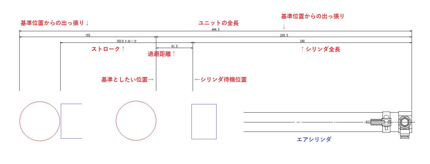
*Important: If you do not note this carefully in the assembly drawing, you may miss some interference, so you should never skip this step.
Please excuse the simplified drawing, as I am unable to provide an assembly drawing.
In 2DCAD, it is common to pattern-copy the model before moving it, erase the hidden lines, and make the solid lines into two dotted lines, but after 3DCAD, this pattern-copying may be a little difficult to express. I will describe this so as not to skimp here.It is recommended to describe the dimensions of this stroke and also the distance from it to the interfering object, etc. It is.
(4) Insert the overall dimensions of the unit and the dimensions of the unit's configuration.
Next, the unit dimensions are put in.
The key to the unit dimensions isI will include the dimensions of the entire unit and the stacking that makes up the unit. The process is to put in the subunit → detail,Unit dimensions should be separated by process, or the dimensions of sub-units, etc. that are assembled prior to their assembly,Carve out dimensions in the order of assembly, etc. There are times when
This is only for ease of assembly, and if it would be difficult to see the dimensions of the unit being included, it will not be listed.
(5) Insert special dimensions
The special dimensions are information on purchased items, etc. Mainly
- Mounting dimensions of purchased products (catalog values)
- Description of special dimensions, fine pitch, and other uncommon parts of purchased items (typical: floating joints, adjusting screws, etc.)
As long as there is no adverse effect on the assembly drawings, we will include the dimensions of the installation pitch of the purchased items and the parts related to their operation.For assembly drawings,The dimensions of purchased items, which are important to the specifications, are included, but they are mostly meant for drawing purposes.It is. In mechanical design, we sometimes download and use CAD data of purchased products. Sometimes that intermediate file is different from the actual product (catalog dimensions), soVery important dimensions to prevent mistakeswill be.
If the dimensions were to be wrong, the impact on other parts would be significant,I include the mounting pitch of the purchased items and the dimensions of the parts related to their operation and check them against the catalog at the end, as long as there are no adverse effects on the assembly drawings.
(6) Insert adjustment dimensions
Adjustment dimensions are, for example, "how much the threaded part should be screwed in" when attaching a floating joint to a rod cylinder,Directed dimensions for assembling parts that should not be assembled properly or where there is no positioning (where adjustments are required).It is.
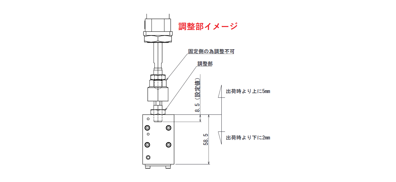
It is also a good idea to draw a detailed drawing or cross section of such a part so that it is easy to see if screws are poking against each other inside the part.
For example, if the adjustment is made by turning a handle, the side of the balloon should be labeled "for 00 adjustment" or something similar.
Furthermore, after adjustment and assembly, it is good to have a dimension that says, "If the distance between where and where is this dimension, it is OK. For example, the distance to other related parts after assembly.This is because a machine is made up of an accumulation of parts (tolerances), so even if it is assembled in the same way as the partial detail drawing, the dimensions may be slightly off as a result.
Supplement: Useful text to have on assembly drawings
From here, we will discuss notes and text that play an important role in assembly drawings in addition to dimensions.
Supplement-1 Size of strength member (steel, shaft diameter, etc.)
Strength members are the steel materials that support the machine It is.By describing the size of the steel material, it will be easier to examine whether the strength of the material is sufficient in advance.
This is especially necessary during the planning phase, so I have included the following information in the assembly drawings for the planning phaseStrength members are listed. and erase it when you get to the details. It is not necessary to list all the components, but only those where special attention should be paid to strength and rigidity in the device. (In fact, this allows the customer to check in advance and make initial requests such as "make it stiffer.)
Supplement-2 Describe what to pay attention to when assembling
What to note when assembling is described where it is "different from the general way of doing things". I will do so.For example, this is a place that is not usually used but should be used only here, such as instructions for "Loctite application" for a specific screw. Tightening torque for screws also falls under this category.
Supplement - 3 Comments on places that may be easily misunderstood
Similar to what you note above during assembly, though,To put comments in places that are easily misunderstood and indistinguishable so that they can be understood.It is.
For example, "RL" is used, but instead of just stating "R side," it should be "R side viewed from upstream," etc. The order of assembly diagrams is also important and should be noted.Just a few things,You should create assembly drawings with the feelings of the people involved in those drawings.I think.
This is the basis of the assembly diagram. That is all.
-

-
Introduction to Mechanical Drawing
Here, I would like to leave a note as an introduction to mechanical drawing, "Thorough Explanation from Basic Rules to Drawing Methods". In mechanical drafting, I have been wondering if I can really convey the ...
See more.
