Here.mechanical drawing inHow to Draw a Parts Diagram." The following is a note on the basics of parts diagrams with regard to
- What is a Parts Drawing?
- Important] Impact of Parts Drawings
- Supplement: Where to check/where not to check before drawing a part drawing
What is a Parts Drawing?
A parts diagram is aIt is a collection of information on the individual parts that make up a machine, and is distinguished from assembly drawings. Here.What is its parts diagram? and other basic information,For those new to parts diagrams Summarizing.
Standards to refer to in drawing parts diagrams
The reference standard for our drawings is JISB0001: Mechanical Drawing, and parts drawings must also basically follow this standard.
Elements Comprising a Parts Diagram
A parts diagram is made up of many elements to carry information on the parts, and is illustrated below.。
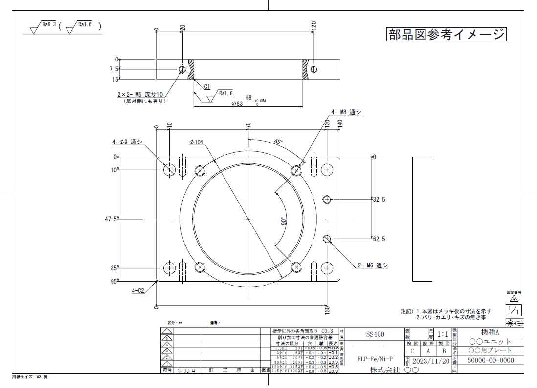
Items Required for Parts Drawing
The parts drawing isThe following items are needed to properly communicate information about the part (You may omit any unnecessary information. (You may omit unnecessary information)
- Figure frame to be used(A1, A2, A3, A4 length and width)
- drawing scale
- Indication of parts (front, plane, side, section, partial detail, oblique view)
- Dimensions(parallel, parallel, progressive)
- tolerance(Dimensional and geometric tolerances)
- Material (with/without pretreatment)
- ProcessingHeat treatment(Surface treatment)
- Surface roughness indication
- Notes and annotations
- hardness
- Destination Unit Name
- Part Name
- Part Number
- General Tolerance
- date of creation (e.g. of a map)
- Revision Date, Revision Number, Revision Details
- Designers, draftsmen, andperson who checks accuracy of a drawing
Types of Parts Drawings
The image above is a standard parts diagram, but parts diagrams can be classified into the following types.
(1) Cutting parts drawing
Parts drawing for machine cutting of metal structural parts
(2) Molded parts drawing
Parts drawing showing injection molded products (resin), etc.
Welded parts drawing / Canning parts drawing
Parts drawings for welding multiple steel materials together to make machine racks, large structures, etc. Since parts cannot be made by welding alone, it is necessary to include machining information in addition to welding instructions.
Sheet Metal Working Drawing
Drawings of parts such as L-shaped brackets and boxes made of sheet metal. Drawings that include instructions for metal bending, welding, partial drilling, etc.
(5) Blank diagram
A drawing showing the part geometry prior to machining. Used to indicate materials to be purchased prior to machining.
⑥ Additional machining diagram
A drawing used for drilling additional holes in purchased parts or performing additional work on parts that have already been produced.
(vii) Revised drawing
In each drawing, a drawing that is revised later after the drawing has been issued (after arrangements have been made). Each company has its own rules for these revised drawings.General Revision Chart Drawing The following is a summary of the results in the following table.
(viii) Hand-drawn drawings
Hand-drawn drawings are not just about parts drawings, though, as there are also hand-drawn assembly drawings,In the machine shop, hand-drawn drawings areThis technique is still needed even now that CAD is widely used as an improvised drawing.
Thus, there are many different types,Each company has its own "writing style" according to its products and environment. The company is doing so.
Important] Impact of Parts Drawings
Drawing a part drawing is the last stronghold to eliminate mistakes for a part, since there may be several people involved in the past for a single part, and it is a heavy task to make a drawing that can be successfully realized.The cost of a part can vary greatly depending on the choice of material, the way it is dimensioned, the tolerances, the range of treatments, the range of hardness, and so on.
The higher cost of parts can be translated into more time-consuming production and longer delivery times, and even if it is only a square block, it is difficult to draw up a parts drawing.
The manufacturer reproduces the actual product in reality based on the drawings.
In other words, it is easy for the manufacturer to understand our ideas, such as how to reproduce the drawings that we, the designers, draw, or what new tools are needed to reproduce the drawings,Need to write what you can certainly make. There are
Supplement: Where to check/where not to check before drawing a part drawing
Lastly, the "APlaces to check before drawing a parts drawing / Places not to checkI will leave a note about the "I'm not sure how to do this, but I'm sure it will work.
In drawing a parts diagramThere are three main phases of critical timing There is a It is
- There's a place to check before you draw a part drawing.
- I have a few things to keep in mind when I'm drawing a parts diagram.
- I have a place to look at it after I've drawn the part drawings.
It is.
Drawing a parts diagram means that for a single part, the pastMore than one person has been involved. I think it is actually more likely that someone else will generate a parts drawing from a model that someone else has done.
in that caseI have the impression that if the scope of work is not clearly defined, mistakes will just flow on and on, and it will be very difficult. The parts diagram is a part of theIt is the last bastion for the parts to get rid of mistakes and to materialize them safely.Need to check for completeness and avoid duplicate checks from a drafting cost perspective. I guess that is what it is all about.
As a common thought of draftsmen,There is an assumption that the part for which the part drawing is to be created is "already designed" or "it has a strange shape, but there must be an intention for it to be this way. It is.
(1) Things to check before drafting
1-1 Check if the hole position and hole size are correct with the mating parts.
First of all, it is a mating part for the part drawing target.Check if the position and size of the holes match the holes in the manufactured or purchased product. I will do so.
At this time, the position of the holes in the purchased product is checked at the last drawing inspection, so there is no need to compare with the catalog at this time, and at that point, we check if there are any mistakes between the models. In the case of 3D CAD, however, the evaluation can be made as it is seen because it is three-dimensional,In case of 2DCAD, bring 3 planes and check if the shape and triangulation method are correct. I will do so.
In some cases, part drawings are generated without knowing how much detail the previous designer has provided. Therefore, it is necessary to check the data here, and if there is a problem, it must be cleaned up (either by having it corrected or by yourself) before generating the part drawing. Also, this part isI think it is desirable to check one item at a time when creating a parts drawing.
Check for stationary interference at the corners and edges.
As with screw size, corner as a serious interference,Corner mistake There are
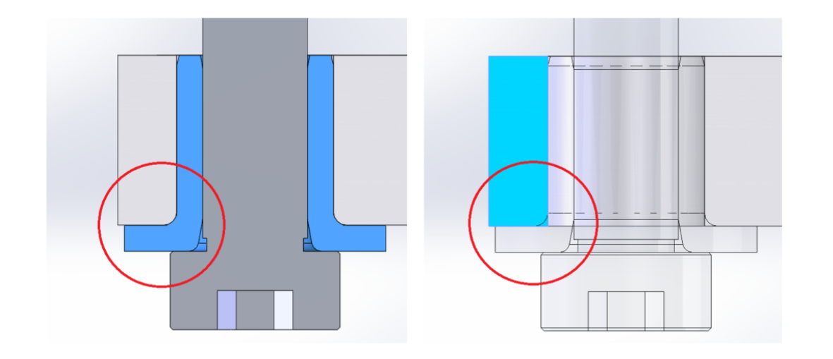
This model is a good example,Since 3DCAD has a function for replacing components, the parts before replacement were fine, but the pattern of interference caused by the replacement was missed. And these places arePoints that are often overlooked by designers It is.
These small places are alsoWhere to find it before drawing a parts diagram. It is.
①-3 Check the elements required for the subject parts.
This is a very important process. Looking at the model
- The purpose for which the part to be drafted is needed and the elements it should have
- What is the standard for stable production?
and confirm the results.
The component is.What tolerances and posture should be in place for the machine to perform its correct role andWhere should those parts be made? and their relationship to the surrounding components,This will be expressed in the dimensioning and posture tolerances that follow.
These are the three points above. These do not have to be done if you are told in advance that you do not need the check,A task so important that it could be called a draftsman's job if not told. So, make sure to check for sure.
(2) Areas that do not need to be confirmed and areas that should not be modified or changed without permission
On the other hand, there is a part that takes time and effort if you bother to check it.
2-1 Basically no need to check for interference in the operating state
Checking for interference in the operating state is basically the designer's job, so confirmation is not necessary. but if it is found, check it and have it corrected.
2-2 No modification without permission
No unauthorized modifications should be made prior to drawing the part drawing. The reason for this is thatAssuming that the shape is meaningful. This is because we are making the
When generating a parts drawingWe sometimes see shapes and holes whose purpose or intent is unknown. Basically, we are modeling shapes whose use is unknown with their own purpose during the design process.
For example.
- It's a part that would be less expensive to machine through, but it's machined at the stop.
- There is a tap with an unknown purpose that is not attached to a screw.
- I've made it more than 2 parts when I could have gone with 1 part.
- Somehow there is a spacer in between.
Such as.
The machine parts we design are often composed of metal, and some of them are too heavy for people to easily carry.
Taps are often used to install or fine-tune such parts. The tap is often used to install or fine-tune such parts.The basic rule is not to touch the model so as not to erase meaningful parts. It is advisable to approve it before drafting with
In brief
The draftsman drafts the parts by looking at each part one by one when drafting the parts to see if there are any pokashi-misses or interferences at rest with things that have a clear purpose (fastening), and drafts the parts by checking the purpose for structures that cannot be grasped up to the purpose, but may have a reason. This will be the case.
(The detail of the part drawing in 2D CAD will be generated by the part drawing depending on the designer's finish. Therefore, there is a possibility that a different shape from what the designer had in mind may be drawn on the parts drawing, so some design knowledge is required.
In the case of 3D CAD, it is ideal to complete the 3D model, but since the shape of the part is transferred (synchronized) to the BOM, small changes can be made by modifying the model and importing it after the BOM is completed.
After this, we will finally work on the drawings.
Finally, we can start working on the drawings here.
That's it.
-

-
Introduction to Mechanical Drawing
Here, I would like to leave a note as an introduction to mechanical drawing, "Thorough Explanation from Basic Rules to Drawing Methods". In mechanical drafting, I have been wondering if I can really convey the ...
See more.
